Home
Simrad
Sonar
SU90
Installation Manual
Page 218
Simrad SU90 - Page 218
328 pages
Manual
Save Page as PDF
To Next Page
To Next Page
To Previous Page
To Previous Page
Loading...
Simrad
SU90
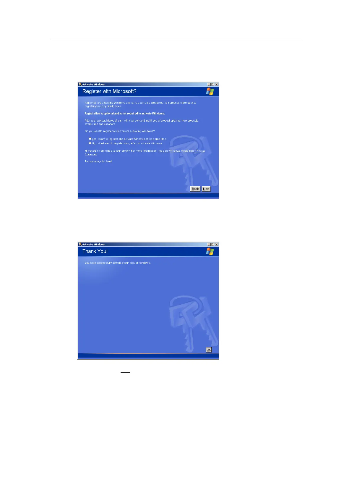
c
Observe
the
following
dialog:
d
Click
No,
I
don't
want
to
register
now
...
.
e
Click
Next
.
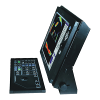
f
Observe
the
following
dialog:
15
If
your
computer
is
not
connected
to
the
Internet.
a
Click
Y
es,
I
want
to
telephone
a
customer
service
r
epr
esentative...
.
b
Click
Next
.
216
381293/A
217
219
Table of Contents
Main Page
Table of Contents
5
About this Manual
15
Simrad Su90
17
System Description
18
System Diagram
20
System Units
21
Colour Display
21
Processor Unit
21
Operating Panel
21
Operating Panel Power Supply
22
Audio Amplifier with Loudspeakers
22
Transceiver Unit
22
Hull Unit
22
Transducer
23
Scope of Supply
23
Main Units Included with the Standard Delivery
23
Additional Items
24
Additional Required Items
24
Colour Display
24
Uninterrupted Power Supply (UPS)
25
Installation Trunk
25
Speed Log
26
Course Gyro
26
Optional Items
27
Hull Unit
27
Installation Trunk
27
Extended Range
28
Scientific Interface
28
Other Peripheral Equipment
28
Audio Output
30
External Motion Reference Unit (MRU)
32
Secondary Operating Panel
32
General Supply Conditions
33
Equipment Responsibility
33
Receipt, Unpacking and Storage
33
General Installation Requirements
34
Supply Power
34
Uninterrupted Power Supply (UPS)
34
Wiring
34
Compass Deviation
35
Noise Sources
35
Dry Docking
35
Approval by Classification Society
35
Support Information
35
Installation Procedure
37
Preparations
39
Installation Drawings
40
Necessary Tools and Equipment
40
Worker Skills
41
Determing the Location of the Hull Unit
42
Fore and Aft Location
42
Athwartships Location
43
Important Considerations Related to Noise
43
Sonar Room Requirements
44
Watertight Integrity
44
Size and Access
45
Heating
45
Insulation
45
Ventilation
45
Cable Protection
46
Electrical Installations and Lights
46
Bilge Pump and Decking
46
Lifting Device
46
Communication
46
Sonar Room Arrangement Example
47
Sonar Room Arrangement Example 1 - Top View
47
Sonar Room Arrangement Example 2 - Side View
48
Hull Unit Orientation Example
49
Acoustic Noise
49
Contributing Noise Factors
50
Self Noise
51
Ambient Noise
53
Fishing Gear Noise
53
Electrical Noise
54
Reverberation
54
Some Means to Reduce the Noise
54
Installing the Sonar Trunk
57
About the Sonar Trunk Installation
58
Mounting the Sonar Trunk
59
Mounting the Trunk Extension
60
Sonar Trunk Installation Principles
61
Installation of a Trunk with Open Blister
62
Installation of a Trunk with Oil Filled Blister
63
Protecting the Sonar Trunk
61
Sonar Trunk Installation Measurements and Check List
64
Installing the Hull Unit
65
About the Hull Unit Installation
66
Hull Unit Familiarization and Main Parts Identification
67
Motor Control Unit Familiarization and Main Parts Identification
68
Hull Unit Models Overview
69
Unpacking the Hull Unit from Its Transport Box
70
Mounting the Hull Unit
72
Bleeding Air Cock
74
Mounting the Mechanical Support
74
Transducer Alignment
75
Visual Inspection of the Transducer
75
Lowering and Hoisting the Transducer Manually Using the Hand Crank
76
Hull Unit Installation Check List
78
Installing the Transceiver Unit
79
Installing the Bridge Units
83
Preparations for Installation
84
Basic Requirements
84
Location of the Colour Display
84
Location of the Processor Unit
85
Location of the Operating Panel
85
Location of the Operating Panel Power Supply
86
Location of the Amplifier and Loudspeakers
86
Maximum Distances between the Units
87
Installation of the Colour Display
87
Installation of the Processor Unit
88
Installation of the Operating Panel
90
Installation of the Operating Panel Power Supply
91
Installation of the Amplifier and Loudspeakers
91
Cable Layout and Interconnections
92
Read this First
93
Cable Plan
95
Bridge Cables
95
Sonar Room Cables
96
List of Cables
97
RJ45 Ethernet, Straight
101
This Cable Must be Provided by the Installation Shipyard
101
Cable Procedures
102
Connecting AC Mains to the Colour Display
102
Connecting Ground to the Operating Panel
102
Connecting the Processor Unit to the Transceiver Unit
102
Connecting the Ethernet Cable for Scientific Output
102
Connecting AC Mains to the Uninterrupted Power Supply
102
Connecting AC Mains to the Transceiver Unit
102
Connecting AC Mains to the Heat Exchanger
102
Connecting AC Mains to the Uninterrupted Power Supply
103
AC Mains with IEC 60320 Socket and Inline Plug
103
The Other End Is Terminated in an AC Connector Suitable for the Local Conditions
103
Connecting the Video Cable from the Processor Unit to the Colour Display
104
DVI-I Display Cable
104
Connecting the USB Cable from the Operating Panel to the Processor Unit
105
Connecting the Dual Interface Cable from the Operating Panel to the Processor Unit
106
Connecting the Operating Panel Power Supply to the Processor Unit
107
AC Mains with IEC 320/C7 Inline Plug
107
Connecting AC Mains and Ground to the Processor Unit
108
AC Mains with IEC 60320 Socket and Inline Plug
108
Vessel Ground
108
Connecting AC Mains to the Colour Display
109
This Cable Is Provided with the Display. It Is a Standard Commercial Mains Cable
109
AC Mains with IEC 60320 Socket and Inline Plug
109
Connecting Ground to the Operating Panel
110
Vessel Ground
110
Connecting the Processor Unit to the Transceiver Unit
111
Connecting AC Mains to the Transceiver Unit
113
AC Mains with IEC 60320 Socket and Inline Plug
113
Connecting AC Mains to the Motor Control Unit
114
Installation Shipyard
114
Connecting the Transceiver Unit to the Motor Control Unit
115
Connecting AC Mains to the Heat Exchanger
116
Connecting the Ethernet Cable for Scientific Output
117
RJ45 Ethernet, Straight
117
Connecting the Audio Cables for External Powered Speakers
118
Connecting the Transducer Cable
119
Connecting the Interface Cables to the Peripheral Equipment
119
Moxa CP114EL-I Serial Adapter Setup
119
Serial Line Support
120
Jumper and DIP Switch Settings
120
Software Setup (Windows XP)
120
Software Setup (Windows 7)
122
Adapter Cable
123
References to Detailed Cable Drawings and Specifications
125
Generic RS-232 Serial Line (Three Wires)
125
Used as External Trigger Input or Output
125
Generic RS-422 Serial Line (Five Wires)
125
Interfacing Peripheral Equipment
126
Connecting the Speed Log
126
Overview of Interfaces and Supported Telegram Formats
127
Telegrams Received from External Devices
127
Telegrams Sent to External Devices
129
Monitoring and Changing the Interface Settings
130
Default Interface Settings
130
Changing the Interface Settings
131
Monitoring the Traffic on a Serial or Ethernet Line
134
Synchronisation with Other Acoustic Systems
137
Setting up the Synchronisation Function
137
About Synchronisation
139
Synchronisation Using a Serial Line
140
SU90 Set up as Slave
140
SU90 Set up as Master
140
Synchronisation Sequences
141
Synchronisation of the Sonar Clock with an External Clock
142
Opening the Installation Menu
143
Changing the Necessary Parameter to Allow for Clock Synchronization
143
Connecting the Speed Log and Course Gyro
143
Connecting the Course Gyro
143
Connecting the Speed Log
144
Installation Shipyard
144
Configuring and Testing the Interface to the Speed Log
144
Connecting the Course Gyro
145
Installation Shipyard
145
Configuring and Testing the Interface to the Course Gyro
145
Connecting an External Motion Reference Unit (MRU)
146
Physical Installation of the Motion Reference Unit
146
Installation of the Motion Reference Unit Cable
146
Opening the Installation Menu
147
Configuring and Testing the Interface to the Motion Reference Unit
147
Entering the Stabilisation Offset Angle into the SU90
148
Connecting a Secondary Operating Panel
149
Parts and Tools Required to Install a Secondary Operating Panel
149
Physical Installation of the Operating Panel
150
Installation of the Operating Panel Cables
150
Opening the Installation Menu
151
Configuring and Testing the Interface to the Secondary Operating Panel
152
Cable Plan for a Secondary Operating Panel
153
List of Cables Required for the Secondary Operating Panel
154
This Cable Is Provided with the Power Supply, It Is Often Physically Fixed to the Unit
154
This Cable Is Provided with the SU90 Operating Panel. It Is a Standard USB Data Cable with Length 4,5 Meters
154
Universal Serial Bus (USB)
154
This Cable Is Provided with the SU90 Operating Panel. It Is a Special Dual Cable
154
With One Common 15-Pin Connector Leading to Two Separate 9-Pin Connectors in
154
The Two Other Ends of the Cable. the Cable Length Is 4,5 Meter
154
Operating Panel "Dual" Cable
154
If this Is Not the Case, You Must Replace the AC Connector. the Typical Cable
154
Length Is between 1,5 and 2 Meters. if this Is too Short You Must Use an Extension
154
AC Mains with IEC 60320 Socket and Inline Plug
155
C10 SU90/C10 Operating Panel USB Cable to Processor Unit
155
C11 SU90/C11 Operating Panel "Dual Cable" to Processor Unit
155
Cable (Not Recommended), Mount a New Power Outlet Within Range, or Make Your Own Power Cable
155
If this Is Not the Case, You Must Replace the AC Connector. the Typical Cable
155
Length Is between 1,5 and 2 Meters. if this Is too Short You Must Use an Extension
155
The Other End Is Terminated in an AC Connector Suitable for the Local Conditions
155
Establishing Emergency Hoist Functionality
156
Designing the Emergency Hoist Interface
156
Circuit Board Interface Description
157
Testing the Interfaces to Peripheral Devices
158
Opening the Installation Menu
158
Configuring and Testing the Interface to the Positioning System (GPS)
158
Configuring and Testing the Interface to the Speed Log
159
Configuring and Testing the Interface to the Course Gyro
160
Configuring and Testing the Interface to the Positioning System (GPS)
161
Configuring and Testing the Interface to a Trawl System
162
Configuring and Testing the Interface to a Catch Monitoring System
163
Configuring and Testing the Interface to a Radio Buoy System
163
Configuring and Testing the Interface to a Sea Current Meter
164
Setting to Work
165
Starting up the Hull Unit
166
Hull Unit Familiarization and Main Parts Identification
167
Motor Control Unit Familiarization and Main Parts Identification
168
Functional Check
168
Apply 3-Phase AC Power
169
Check the Hoisting Motor's 3-Phase AC Connections
170
Check 3-Phase Connection for Correct Rotation
171
Check the K301 Contactor Operation
172
Verify Correct Hoist and Lower Functionality
173
Starting up the Bridge Units
175
Starting up of the Processor Unit for the First Time
175
Setting up the Sonar to Retrieve Simulated Sonar Echoes
176
Opening the Installation Menu
176
Checking the Operating Panel
177
Operating Panel Functional Tests
177
Checking the Operating Panel Backlight
182
Powering off the Sonar
183
Starting up the Transceiver Unit
183
Checking the Hoist/Lower Functionality
185
Connecting the Transceiver Unit to the Processor Unit
185
Selecting Which Hull Unit Type to be Used
186
Checking the Hoist/Lower Functionality from the Bridge
187
Checking the Hoist/Lower Functionality from the Sonar Room
189
Measuring the Self-Noise
190
Starting up the SU90 System
192
Preparations before the SU90 System Is Started
192
Starting up the SU90 System, Bridge Actions
193
Starting up the SU90 System, Sonar Room Actions
194
Alignment of the Sonar Picture
195
Adjusting the Stabilisation Sensor Offset
196
Estimating the Offset Angle
196
Entering the Stabilisation Offset Angle into the SU90
197
Defining Own Ship Parameters
197
Specifying Ship Dimensions
197
Specifying Instrument Position Offsets
198
Opening the Installation Menu
198
Final Tests and Measurements
200
Source Level (SL) Measurements
201
Preparations and Test Hydrophone Data
201
Test Setup
202
Sonar Parameters
202
Test Procedure
203
Finalizing the Procedure
204
Source Level Test Results
204
Receiving Voltage Response (VR) Measurements
205
Preparations
205
Sonar Parameters
205
Test Procedure
206
Finalizing the Procedure
207
Receiving Voltage Response Test Results
207
Noise/Speed Curve Measurements
208
Preparations
208
Test Procedure
208
Problems with Flow Noise
209
Noise/Speed Test Results
209
Processor Unit Backup and Restore
212
About SU90 Backup and Restore
212
Creating a Backup Image of All the Sonar Software
213
Restoring the Sonar Software from a Backup Image
214
Reactivating the Windows License
215
Creating a Bootable USB Memory Stick
220
Technical Specifications
221
Performance Specifications
222
Weights and Outline Dimensions
223
Environmental Specifications
225
Power Specifications
225
Minimum Display Requirements
226
Telegram Formats
228
Telegrams Received and Sent by the SU90
229
Course Gyro Telegrams
229
Speed Log Telegrams
229
GPS Telegrams
230
ITI and Trawl System Telegram
230
Echo Sounder Telegrams
231
Wind Sensor Telegrams
232
Sea Current Telegrams
232
Catch Monitoring System Telegrams
232
Buoy Telegrams
232
Target Output Telegrams
232
About the NMEA Telegram Format
233
National Marine Electronics Association (NMEA)
233
NMEA Telegram Principles
234
Standard NMEA 0183 Communication Parameters
234
NMEA Sentence Structure
234
Specification of NMEA Telegrams
235
DBS Depth below Surface
236
DBT Depth below Transducer
236
DPT Depth
236
GGA Global Positioning System Fix Data
237
GLL Geographical Position Latitude/Longitude
237
HDG Heading, Deviation and Variation
238
HDM Heading, Magnetic
239
HDT Heading, True
239
MWD Wind Direction and Speed
239
MWV Wind Speed and Angle
240
RMC Recommended Minimum Specific GNSS Data
240
VBW Dual Ground and Water Speed
240
VHW Water Speed and Heading
241
VTG Course over Ground & Ground Speed
242
VWR Relative (Apparent) Wind Speed and Angle
242
ZDA Time and Date
242
Proprietary Telegrams and Formats
243
DBS Depth of Trawl below Surface
244
FS3300 Binary Depth
244
GLL Trawl Position
244
HFB Trawl Headrope to Footrope and Bottom
245
MDS Measured Data Shoal
245
MTW Water Temperature at the Trawl
246
PSIMP-D PI Sensor Data
246
PSIMP-F PI Sensor Data
248
TDS Trawl Door Spread
248
TFI Trawl Filling
249
TPC Trawl Position in Cartesian Coordinates
249
TPP Tracked Target Position or Marker
249
TPT Trawl Position True Vessel
250
TS2 Trawl Spread 2
250
TTS Trawl to Shoal Distance
250
Proprietary Third Party Telegrams and Formats
252
Furuno CIF Sea Current
252
Kaijo VDVCD Vector Current Direction
255
Ryokosei RBY Buoy Input
255
Serpe BSC Buoy Input
256
Drawing File
257
Cabinet Outline Drawings
258
Transceiver Unit Dimensions
259
Processor Unit Dimensions
262
Operating Panel Dimensions
263
Hull Unit Drawings
264
SU92 Hull Unit Dimensions Drawing
265
SU93 Hull Unit Dimensions Drawing
267
SU92/SU93 Mounting Trunk Production Drawing
269
SU92/SU93 Extension Trunk Production Drawing
271
SU92/SU93 Blind Cover Drawing
273
General Safety Rules
274
Equipment Handling
275
Lifting
276
Transportation
276
Storage Prior to Installation or Use
277
Inspection
278
Unpacking
278
General Unpacking Procedure
278
Unpacking Electronic and Electromechanical Units
279
Unpacking Mechanical Units
279
Unpacking Transducers
279
Storage after Unpacking
280
Storage after Use
280
Cleaning Cabinets
280
Mechanical Units
281
Cables
281
Internal Batteries
281
Dehumidifier
282
Coatings
282
Re-Packaging
282
Temperature Protection
282
Circuit Board Handling and Packaging
283
Disposal
284
Electro-Static Discharge (ESD)
284
Su90 Cable Details
286
Cables to Peripheral Devices
287
Positioning System Interface
288
Echo Sounder System Interface
288
Trawl Sonar Interface
288
Catch Monitoring System Interface
289
Current Meter Interface
289
Radio Buoys Connection Interface
289
Cabling Principles
287
Cable Drawings
290
Moxa CP114EL-I Serial Line Adapter
290
Generic RS-232 Serial Line (Three Wires)
291
RS-232 Used as External Trigger Input or Output
292
Generic RS-422 Serial Line (Five Wires)
293
Moxa CP114EL-I Serial Line Adapter
294
Moxa CP114EL-I Serial Adapter Setup
295
Mini-Jack to Phono Audio Cable
296
Vessel Ground
297
AC Mains with IEC 60320 Socket and Inline Plug
298
3-Phase AC Mains to Motor Control Unit
299
AC Mains with IEC 320/C7 Inline Plug
300
Connecting the Operating Panel Power Supply to the Processor Unit
300
Operating Panel Power Supply
301
RJ45 Ethernet, Straight
302
Universal Serial Bus (USB)
304
Connecting the USB Cable from the Operating Panel to the Processor Unit
304
DVI-I Display Cable
305
Commercial Powered Speaker System
306
Operating Panel "Dual" Cable
308
Connecting the Dual Interface Cable from the Operating Panel to the Processor Unit
308
Basic Cable Requirements
309
Cable Trays
310
Radio Frequency Interference
310
Grounding
311
Physical Protection
311
Cable Connections
312
Cable Identification
312
Cable Terminations
312
Installation Remarks
313
Other manuals for Simrad SU90
Operator's Manual
178 pages
Quick Start Guide
72 pages
Harbour Acceptance Test
62 pages
Related product manuals
Simrad ST90
190 pages
Simrad SP70
176 pages
Simrad StructureScan LSS-1
16 pages
Simrad SX90 - INSTALLATION REV C
246 pages
Simrad NSS7
68 pages
Simrad FS 70
114 pages
Simrad forwardscan
6 pages
Simrad TV80
306 pages
Simrad NSS8
68 pages
Simrad EQ60
210 pages