SimradSU90
U2
1
Vcc
Inhibit
HLU “Up”
+24Vdc
2
3
4
Q2
R40
SW1
LED
U7
R39
R48
LK1
GND
P9
R10
R38
CPU
(CD09041 1-001/305166/A)
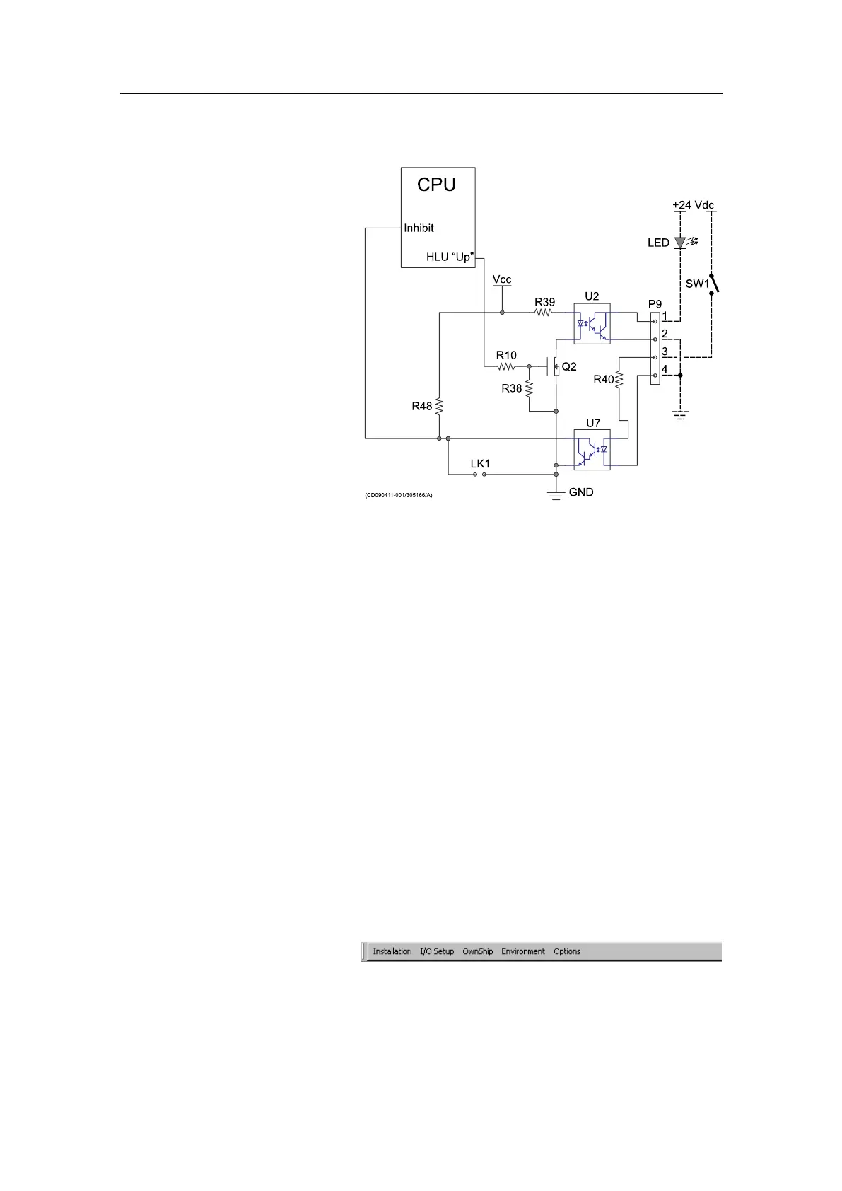
Theexcerptfromthecircuit
diagramexplainstheinterface
circuitry.
+24Vdcconnectedthrough
asuggested“Hoist”switch
SW1topin3willopentheU7
opto-coupler,andthe“Inhibit”
inputonthemicroprocessor
willgo“low”.Thiswillforce
animmediate“hoist”pulse
tothemotor.Simultaneously,
opto-couplerU2willbe
opened,andthesuggestedLED
onoutputpin1willbelitto
indicatethatthetransduceris
hoisted.
Testingtheinterfacestoperipheraldevices
Observetheindividualtestproceduresforthevariousinterfaces.
Topics
•OpeningtheInstallationmenuonpage156
•Conguringandtestingtheinterfacetothespeedlogonpage157
•Conguringandtestingtheinterfacetothecoursegyroonpage158
•Conguringandtestingtheinterfacetothepositioningsystem(GPS)onpage159
•Conguringandtestingtheinterfacetoatrawlsystemonpage160
•Conguringandtestingtheinterfacetoacatchmonitoringsystemonpage161
•Conguringandtestingtheinterfacetoaradiobuoysystemonpage161
•Conguringandtestingtheinterfacetoaseacurrentmeteronpage162
OpeningtheInstallationmenu
Purpose
ThisprocedureexplainshowtoopentheInstallationmenuontheSU90ProcessorUnit.
Procedure
1ClicktheSetuptabonthe
righthandsidetoopentheSetupmenu.
2ClicktheTestbuttontoopentheSystemTestmenu.
3ClicktheInstallationMenubutton.
4ObservethattheInstallationmenuappearsatthetopofthedisplay.
156
381293/A