EM500 Open-Loop Vector Control Inverter User Manual
183
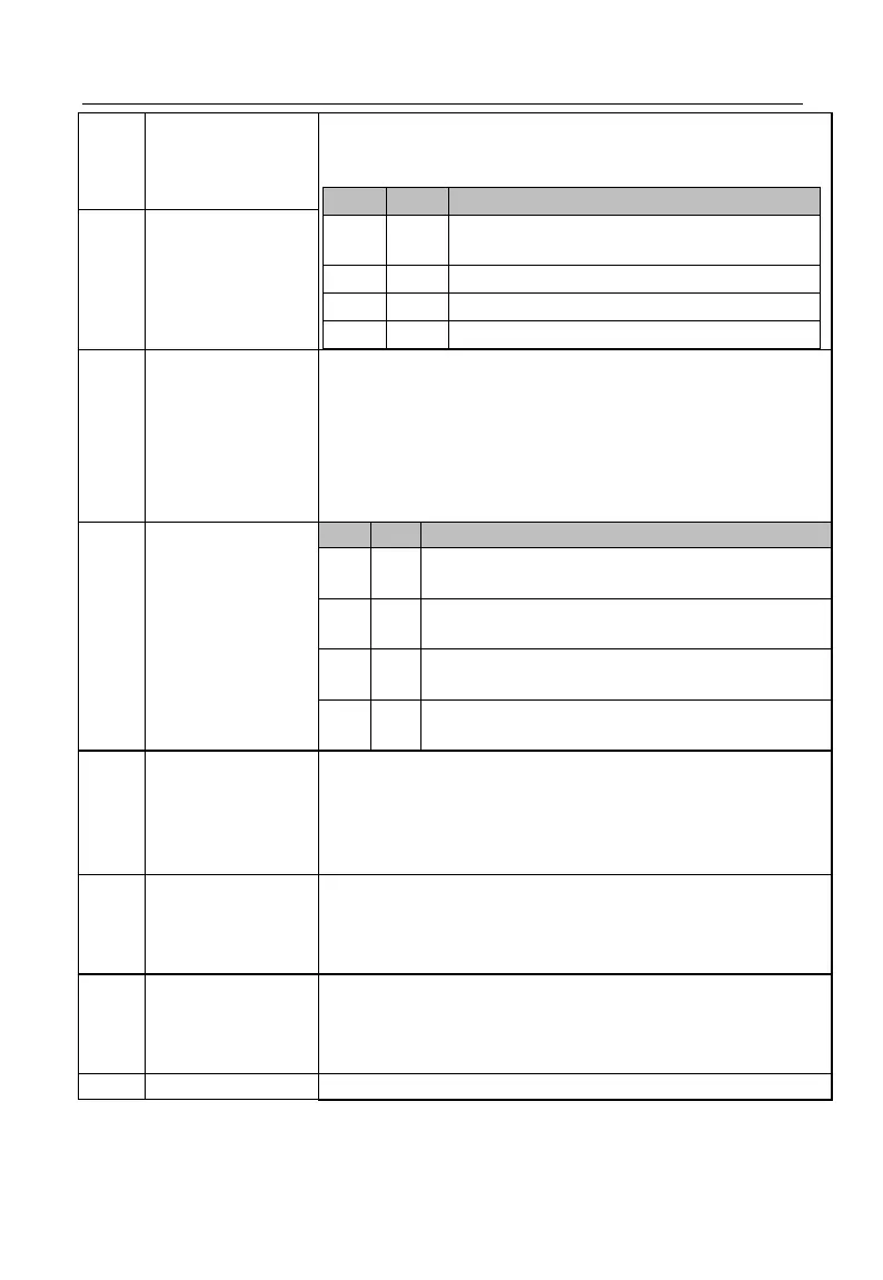
With these two terminals, inverter can realize 4 torque
settings. See the table below (0/1: Present function terminal is
disabled / enabled) or table 7-19.
Determined by the torque setting source
(F13.01)
Acceleration/Decele
ration Time
Terminal 1
EM500 inverter has four groups of acceleration/deceleration
terminals, each group having two input terminals for
acceleration and deceleration. The setting of the combined
code of the 4 terminals, and relevant functions determines
present acceleration/deceleration time. As stated in the
following table: (0/1: Present function terminal
disabled/enabled). See function codes F15.03 - F15.13.
Acceleration/Decele
ration Time
Terminal 2
Acceleration/Deceleration Time
Group 1 (Acceleration Time: F00.14,
Deceleration Time: F00.15)
Group 2 (Acceleration Time: F15.03,
Deceleration Time: F15.04)
Group 3 (Acceleration Time: F15.05,
Deceleration Time: F15.06)
Group 4 (Acceleration Time: F15.07,
Deceleration Time: F15.08)
Acceleration/Decele
ration Prohibited
If the acceleration/deceleration time terminal is disabled, the
command for acceleration/deceleration is prohibited and
inverter’s output frequency remains the same. If inverter is
under the overcurrent protection status, run inverter as per
current limit mode.
Inverter ramps to stop, but all running parameters are
memorized, for example PLC parameter and PID parameter. If
the terminal is disabled, inverter is reset to the pre-stop
running status.
The fault signal of external devices can be inputted through
this terminal, so that inverter monitors and protects peripherals
at fault. Upon receiving external fault signal, inverter displays
“E14”, and coast to stop.
Together with F00.02, these two terminals determine the
 Loading...


