EM500 Open-Loop Vector Control Inverter User Manual
182
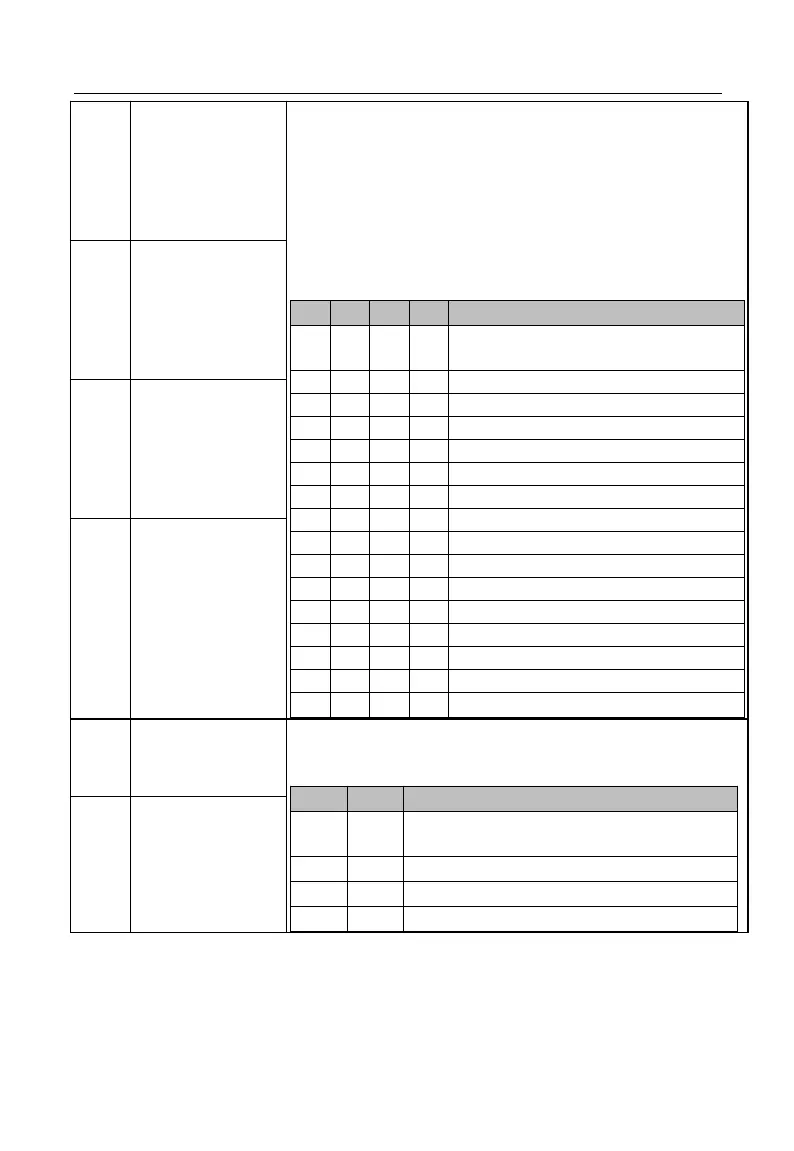
If inverter is in the speed control mode and main frequency
soure A is involved in setting, user can define 4 function input
terminals as preset speed terminals. The combined code of the
4 terminals and the setting of relevant function codes
determine present frequency setting of inverter. As stated in
the following table: (0/1: Present function terminal
disabled/enabled). See table 7–10.
★ If no option has been selected for the input terminal of a
function, the default value is 0 (disabled).
Inverter Setting Frequency
Determined by main frequency
source A (F00.04)
With these two terminals, inverter can realize 4 preset PID
settings. See the table below (0/1: Present function terminal is
disabled / enabled) or table 7-16.
Determined by PID setting source
(F09.00)
Preset PID Setting 1 (F09.32)
Preset PID Setting 2 (F09.33)
Preset PID Setting 3 (F09.34)
 Loading...


