EM500 Open-Loop Vector Control Inverter User Manual
189
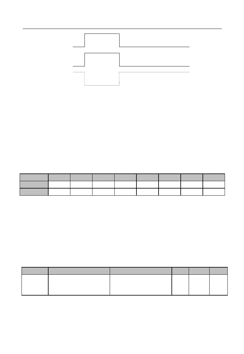
反逻辑采样
有效
无效
无效
有效
Xi Input
On
Off
Positive Logic
Sampling
Enabled Disabled
Enabled
Disabled
Reverse Logic
Sampling
Figure 7-7 Terminal Positive and Negative Logic Sampling
0: enabled when the multi-function input terminal is on, disabled when the
multi-function input terminal is off;
1: enabled when the multi-function input terminal is off, disabled when the
multi-function input terminal is on
Such function codes are under the bit operation. Set corresponding position as 0 or
1 while setting them. Take F02.15 as example (see the table below):
Table 7-5 Function Code of Bit Operation
The 7
th
bit will not be used. This bit can not be set and the displayed value does not
have any meaning.
For example: set X1 to negative logic by setting its corresponding bit 0 as 1, i.e.,
F02.15=xxx xxxx1.
Set X1 and X6 to negative logic by setting corresponding bit 0 of X1 and
corresponding bit of X6 as 1, i.e., 02.15=xx1 xxxx1.
★ This function is used for matching with the logic of other peripherals
Filter Times of
Numeric Input
Terminal
0-100, 0 for No Filter, n
for sampling once every
n ms