EM500 Open-Loop Vector Control Inverter User Manual
207
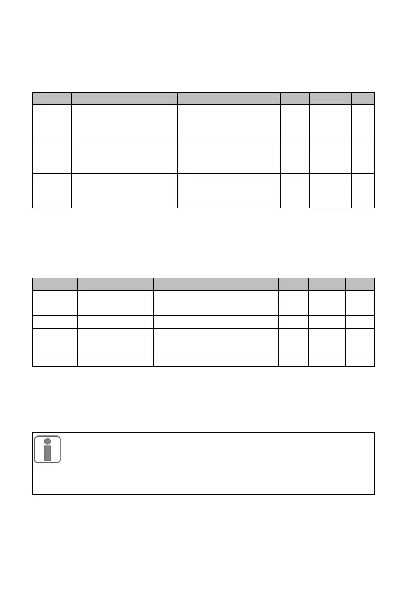
Maximum Frequency of
Y2 High-Frequency
Pulse Output
Minimum Frequency of
Y2 High-Frequency
Pulse Output
Filter Time of Y2
High-Frequency Pulse
Output
High-Frequency Pulse Output Rating: As indicated in Table 7-7, for output of
100.0%, the setting shall correspond to maximum output frequency; for output of 0.0%,
the setting shall correspond to minimum output frequency; output between 100.0% and
0.0% maintains a linear relationship with setting values.
F03.26 performs first-order inertia filter with respect to output.
These function codes are used to correct the zero shift and output amplitude
deviation of the analog output generally, and they can also be used to define the desired
AO output curve to meet different instrument or other requirements. If use “b” for offset,
“k” for gain, “Y” for actual output, and “X” for standard output, then the actual output is:
1. In order to meet the requirements of various instruments or peripherals, the
full-scale voltage of M1 and M2 is 10.9V actually and the full-scale current
2. The default settings of M1 and M2 are 0.00 - 10.00 V.
3. Please use a multimeter to test the idling output of terminals M1 and M2, if
there is high requirement on the accuracy of the analog output.