1-5
IM 701210-05E
Names and Functions of Parts
1
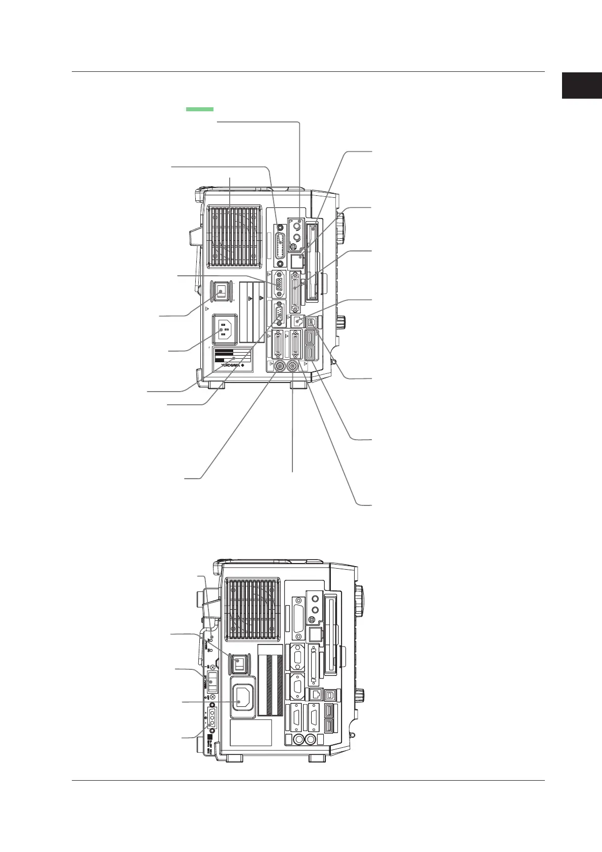
Left Side Panel
DL750
REC LEVEL VOLUME
VOIC E IN/OUT/SW
GP-IB (IEEE488)
ON OFF
100-120V/200-240V AC
300VA MAX 50/60Hz
POWER
100BASE-TX
VIDEO OUT (SVGA)
SERIAL (RS-232)
USB
USB PERIPHERAL
LOGIC A
LOGIC B
GO/NO-GO
TRIG OUT/
EXT CLK IN
TRIG IN
LINK
ACT
SCSI
MODEL
NO.
SUFFIX
Made in Japan
Protect the Instrument from vibration or shock when power is ON
(especially for internal hard disk type).
CAUTION
WARNING
Do not operate without reading safety precautions In user`s manual .
Vent holes
GP-IB connector
Used when carrying out
communications via the
GP-IB interface.
For a description of the
communication function,
see the Communication
Interface User’s Manual.
Voice memo function terminal
Used when recording voice while data acquisition is in
progress using the voice memo function and recording
voice along with screen image data. For a description
of their use, see sections 7.9 and 13.19.
Floppy disk drive, Zip disk drive,
(DL750 only) or PC card drive
Used when saving data to a floppy
disk, Zip disk, or PC card.
For a description of their use,
see section 13.1.
Video signal output
terminal
Outputs the displayed
image using SVGA RGB
signals. For a description
on how to use the terminal,
see section 14.4.
Ethernet port (100BASE-TX)
Used when connecting to a LAN.
For a description of how to use
the port, see section 16.1.
Power switch
For the power ON/OFF
operation, see section 3.4.
Name plate
Power connector
For details on
connecting the power,
see section 3.4.
SCSI interface connector
Used when connecting to a SCSI
device such as a SCSI hard disk.
For a description of how to use
the connector, see section 13.4.
USB connector for connecting
to a PC
Used when connecting a PC with a USB
interface. For a description of how to
use the connector, see communication
interface user’s manual.
GO/NO-GO I/O connector and
external start/stop input connector
Outputs the GO/NO-GO determination
I/O signals.
Also used to externally control the
start/stop of the DL750.
For a description of how to use the
terminal, see sections 11.10 and 14.5.
USB connector for connecting
peripheral devices
Used when connecting a USB keyboard,
USB printer, USB mouse, or USB storage
device.
For a description of how to use the
connector, see sections 4.3 and 12.3.
Logic signal input connector
Used when measuring logic signals.
For a description of how to use the
connector, see section 3.11.
Trigger output/external clock
input terminal
RS-232 interface
Used when inputting external
trigger signals.
For a description of how to
use the terminal,
see section 14.1.
Used when outputting trigger signals
externally or inputting clock signals.
For a description of how to use the
terminal, see sections 14.2 and 14.3.
Used when carrying out
communications with a PC via
the RS-232 interface.
For a description of the
communication function,
see the Communication
Interface User’s Manual.
Trigger input terminal
DC Power Supply Model (DL750 only)
Power supply status LED
Displays the status of the
AC power supply or DC
power supply.
For details on the status
indicator, see section 3.4.
Power switch (AC)
For the power ON/OFF
operation, see section 3.4.
Power switch (DC)
For the power ON/OFF
operation, see section 3.4.
AC power connector
For details on connecting
the power, see section 3.4.
DC power connector
For details on connecting
the power, see section 3.4.
1.1 Top Panel, Front Panel, Right Side Panel, and Left Side Panel

 Loading...


