2-10
IM 701210-05E
2.2 Setting the Horizontal and Vertical Axes
Linear Scaling <Section 5.11>
When measuring the voltage (current), strain, or frequency (number of Rotations/period/
duty cycle/power supply frequency/pulse width/pulse integration/velocity) on the frequency
module, there are two methods of linear scaling: “AX+B” and “P1-P2.”
AX+B
The results obtained from the following computation based on the specified scaling
coefficient A and offset B are displayed as cursor measurement values and automated
measurement values of waveform parameters. You can also assign a unit to the result
of linear scaling. Y=AX+B
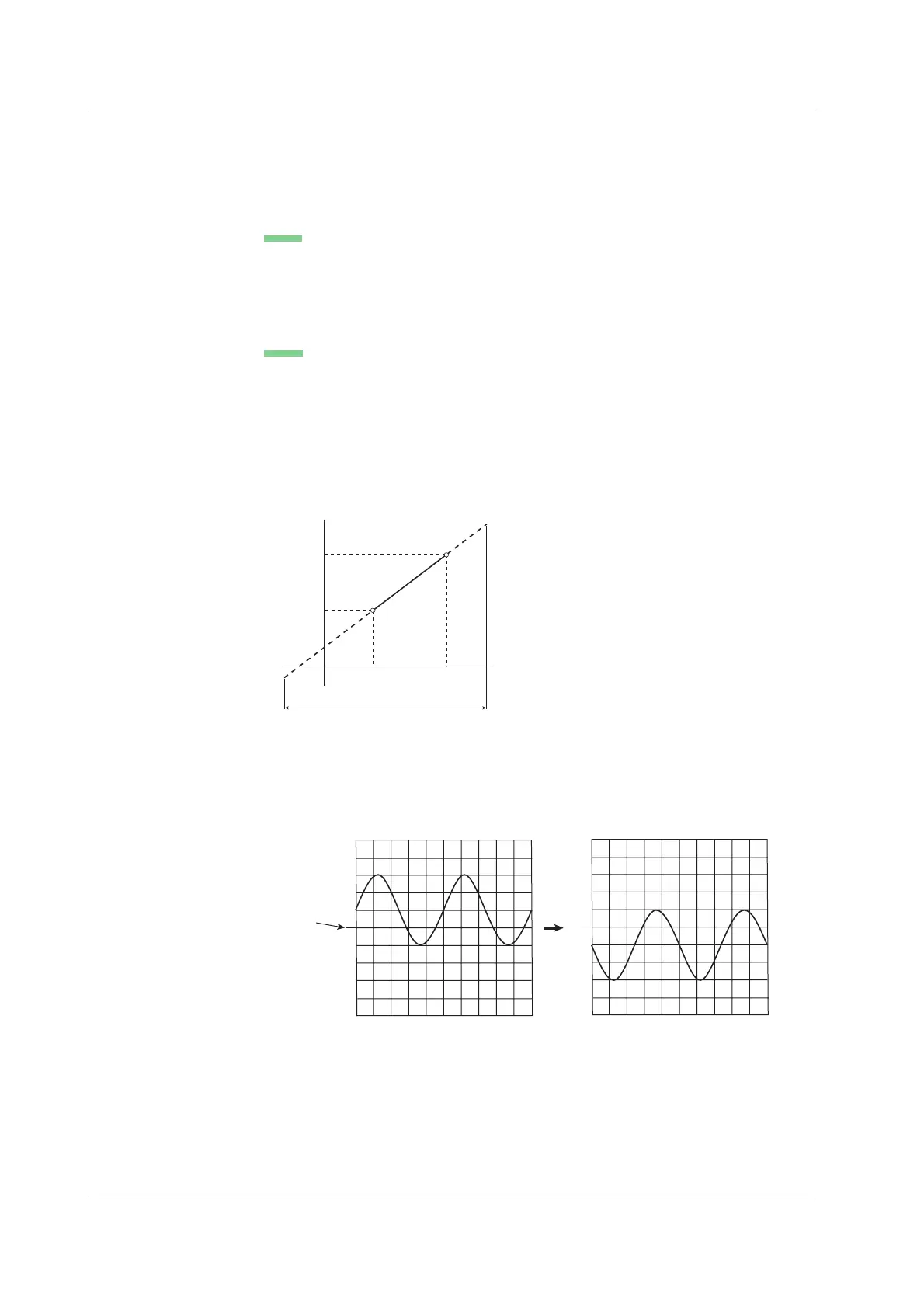
P1-P2
Specify arbitrary scale values (P1:Y and P2:Y) for the measured values of two arbitrary
points (P1:X and P2:X). The scale conversion equation (y = ax + b) is derived from
these four values.
• Range of measured values (P1:X, P2:X): Same as the measurement range
• Range of scale values (P1:Y, P2:Y): –9.9999E+25 to +9.9999E+25
• Initial setting of scale values: P1:X +0.0000E+00, P1:Y +0.0000E+00
P2:X +1.0000E+00, P2:Y +1.0000E+00
Measurement range
P1
P2
P1:X
P2:X
P1:Y
P2:Y
y=ax+b
Measured value
Scale value
In addition, the current input value can be loaded into P1:X or P2:X.
Inverted Display <Section 5.12>
When measuring voltage or strain, the waveform can be displayed with the vertical axis
inverted around the vertical position as shown below.
Vertical
position
mark
Normal display
Inverted display

 Loading...


