Altera Corporation 1–11
July 2005 Stratix Device Handbook, Volume 2
General-Purpose PLLs in Stratix & Stratix GX Devices
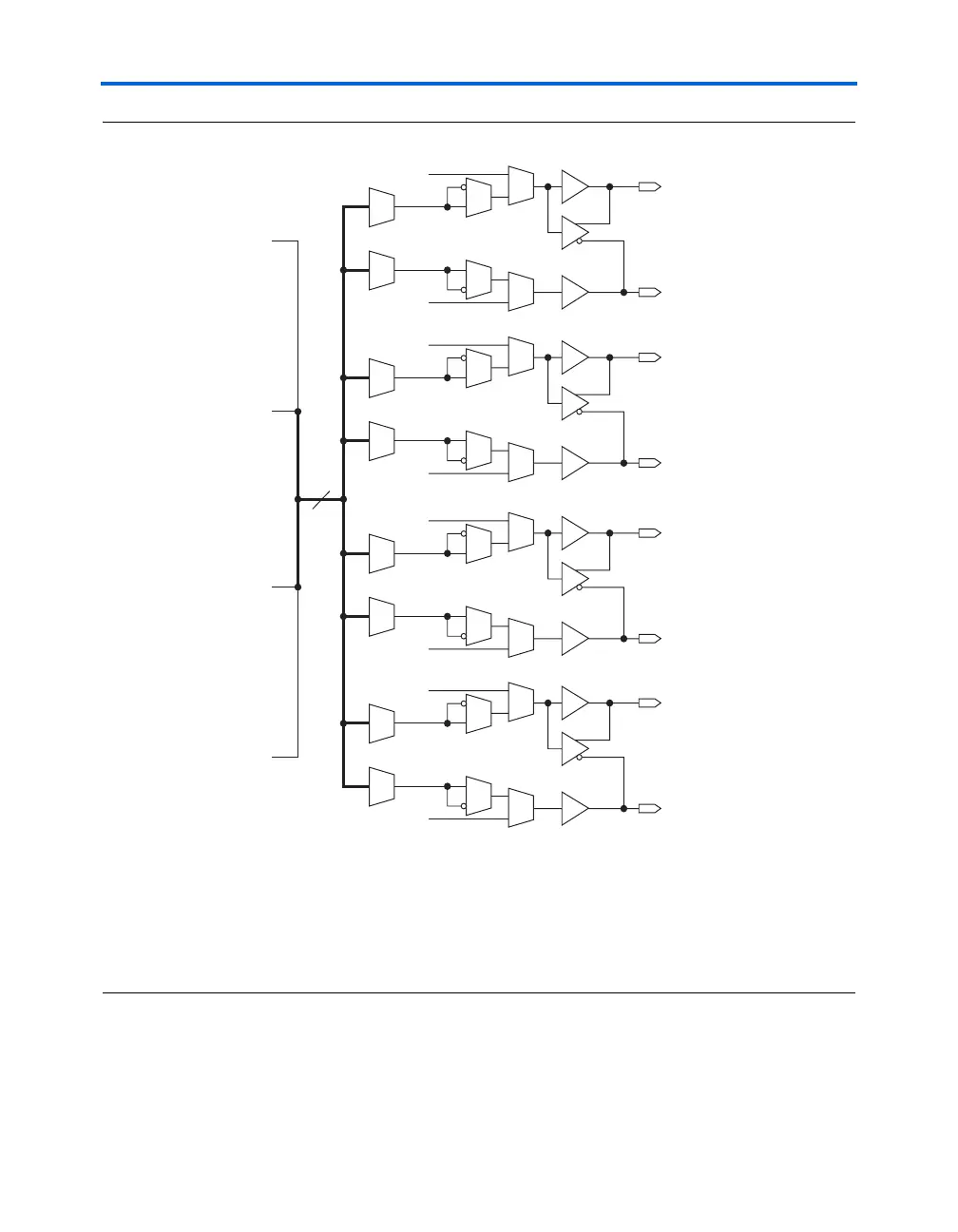
Figure 1–5. External Clock Outputs for PLLs 5 & 6
Notes to Figure 1–5:
(1) LE: logic element.
(2) The design can use each external clock output pin as a general-purpose output pin from the logic array. These pins
are multiplexed with IOE outputs.
(3) Two single-ended outputs are possible per output counter⎯either two outputs of the same frequency and phase or
one shifted 180°.
(4) EP1S10, EP1S20, and EP1S25 devices in 672-pin ball grid array (BGA) and 484- and 672-pin FineLine BGA packages
only have two pairs of external clocks (i.e., pll_out0p, pll_out0n, pll_out1p, and pll_out1n).
Any of the four external output counters can drive the single-ended or
differential clock outputs for PLLs 5 and 6. This means one counter or
frequency can drive all output pins available from PLL 5 or PLL 6. Each
e0 Counter
pll_out0p (3), (4
pll_out0n (3), (4
pll_out1p (3), (4
pll_out1n (3), (4
pll_out2p (3), (4
pll_out2n (3), (4
pll_out3p (3), (4
pll_out3n (3), (4
e1 Counter
e2 Counter
e3 Counter
From IOE (1), (2)
From IOE (1)
From IOE (1)
From IOE (1)
From IOE (1)
From IOE (1)
From IOE (1)
From IOE (1)
4
(3)