7–8 Altera Corporation
Stratix Device Handbook, Volume 2 September 2004
Finite Impulse Response (FIR) Filters
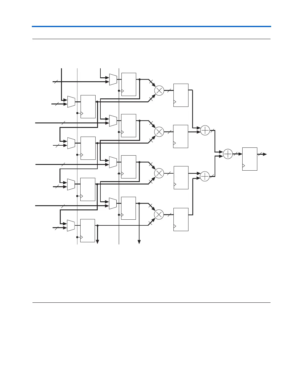
Figure 7–3. Hardware View of a DSP Block in Four-Multipliers Adder Mode Notes (1). (2), (3)
Notes to Figure 7–3:
(1) The input registers feed the multiplier blocks. These registers can increase the DSP block performance, but are
optional. These registers can also function as shift registers if the dedicated shiftin/shiftout signals are used.
(2) The pipeline registers are fed by the multiplier blocks. These registers can increase the DSP block performance, but
are optional.
(3) The output registers register the DSP block output. These registers can increase the DSP block performance, but are
optional.
D Q
D Q
D Q
D Q
D Q
D Q
D Q
D Q
18
18
18
18
18
18
18
18
18
18
18
36
36
36
36
37
37
38
Output
y(n)
x(n)
h(0)
x(n-1)
h(1)
x(n-2)
h(2)
x(n-3)
h(3)
Multiplier D
Multiplier C
Multiplier B
Multiplier A
CLK1
CLR1
CLK2
CLR2
shiftout
input from
previous
block
shiftout
input from
previous
block
Data from
row
interface
block
Coefficients
from row
interface
block
shiftin
input to
next block
shiftin
input to
next block
Data from row
interface block
Data from row
interface block
Data from row
interface block
Coefficients
from row
interface
block
Coefficients
from row
interface
block
Coefficients
from row
interface
block
18
18
18
18
18
D Q
D Q
D Q
D Q
D Q
38