Altera Corporation 7–15
September 2004 Stratix Device Handbook, Volume 2
Implementing High Performance DSP Functions in Stratix & Stratix GX Devices
flops corresponding to h(0), h(2), h(4) and h(6) are enabled. This produces
the temporary output, y
1
, which is added to y
0
to produce the overall
output, y(n). The following shows what the overall output, y(n), equals:
This is identical to the output of the 8-tap filter shown in Figure 7–2. After
cycle 1, this process is repeated at every cycle.
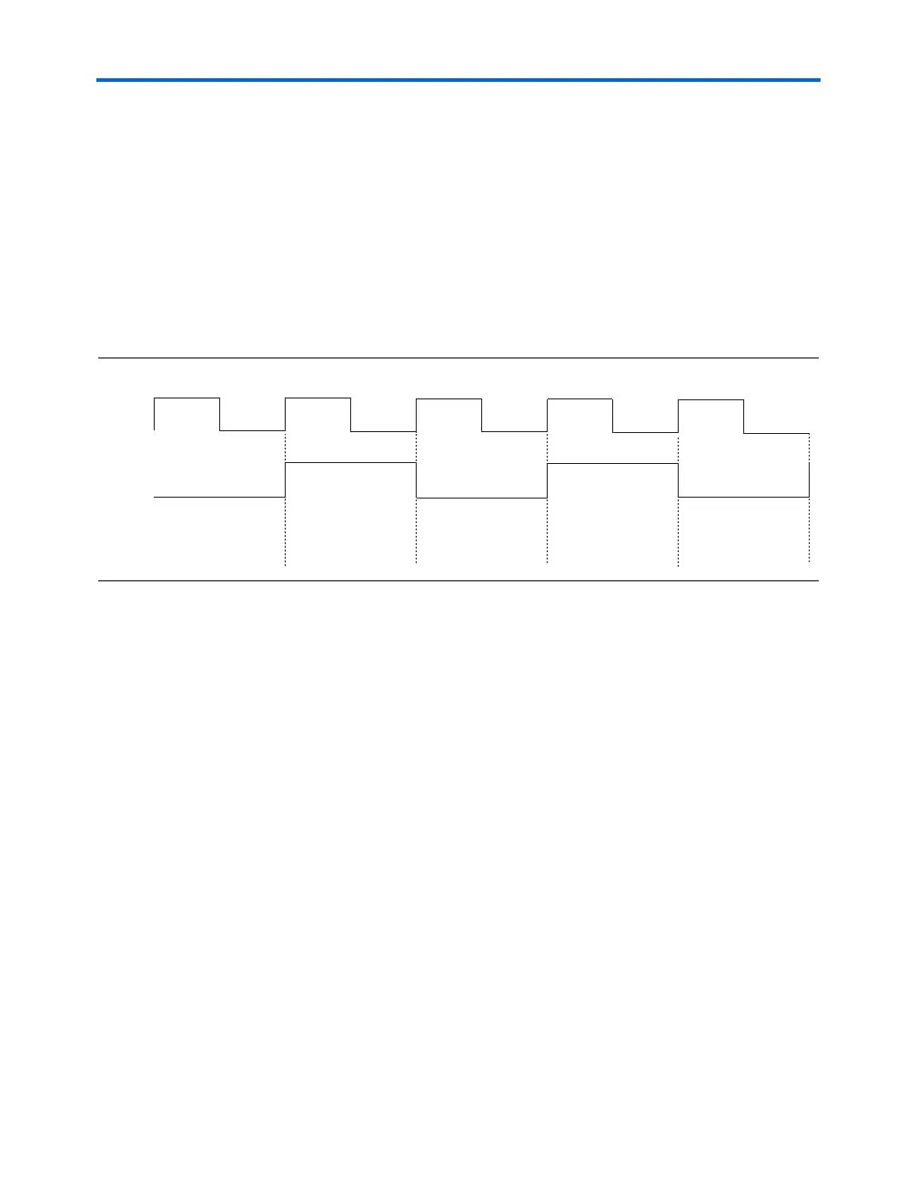
Figure 7–8. Coefficient Loading Schedule in a TDM Filter
yn() y
0
y
1
+=
yn() x0()h0() xn 1–()h1() xn 2–()h2() xn 3–()h3()+++=
+ x n 4–()h4() xn 5–()h5() xn 6–()h6() xn 7–()h7()+++
Cycle 0
load h(1), h(3), h(5), h(7)
Cycle 1
load h(0), h(2), h(4), h(6)
Cycle 2
load h(1), h(3), h(5), h(7)
Cycle 3
load h(0), h(2), h(4), h(6)
Cycle 4
load h(1), h(3), h(5), h(7)
2x clock
1x clock