7–16 Altera Corporation
Stratix Device Handbook, Volume 2 September 2004
Finite Impulse Response (FIR) Filters
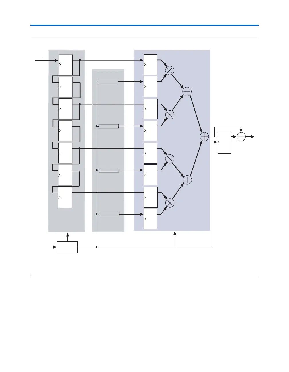
Figure 7–9. TDM FIR Filter Implementation Note (1)
Note to Figure 7–9:
(1) To increase the DSP block performance, include the pipeline and output registers. See Figure 7–3 on page 7–8 for
details.
If the TDM factor is more than 2, then a multiply-accumulator needs to be
implemented. This multiply-accumulator can be implemented using the
soft logic outside the DSP block if all the multipliers of the DSP block are
needed. Alternatively, the multiply-accumulator may be implemented
inside the DSP block if all the multipliers of the DSP block are not needed.
The accumulator needs to be zeroed at the start of each new sample input.
The user also needs a way to store additional sample inputs in memory.
For example, consider a sample rate of r and TDM factor of 4. Then, the
Filter output
y(n)
Clock input
(1x clock)
1x
l
PLL
DQ
DQ
DQ
DQ
DQ
DQ
DQ
DQ
2x clock
DSP block
RAM
R
M
RAM
R
M 1
RAM
R
M
RAM
ROM
Filt
r
o
ffi
i
nt
D
Q
Accumulator
Shift re
iste