Altera Corporation 7–21
September 2004 Stratix Device Handbook, Volume 2
Implementing High Performance DSP Functions in Stratix & Stratix GX Devices
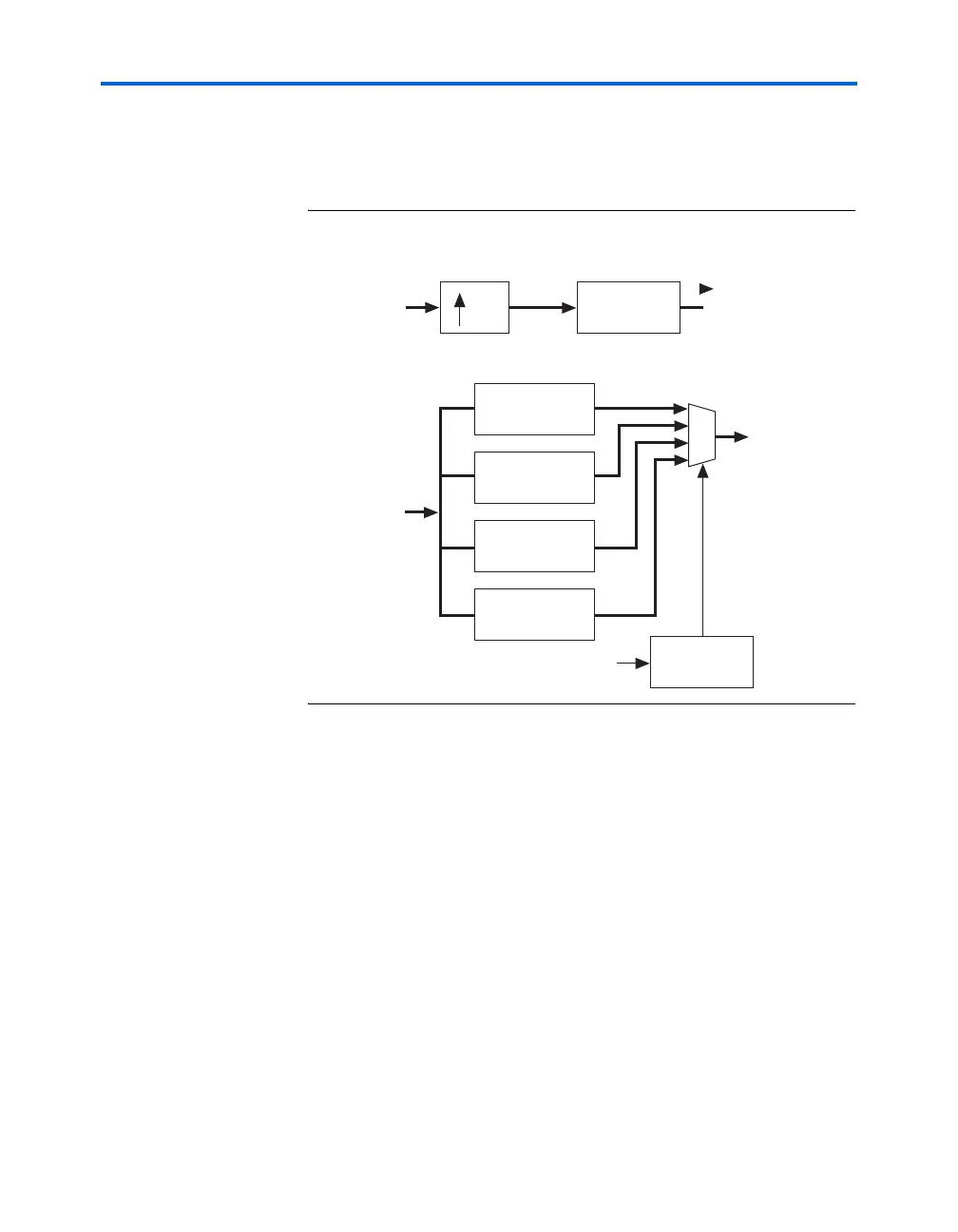
required is 16 × I = 16 × 4 = 64. In the polyphase implementation, the
number of computations per cycle required is 4
× 4 = 16. This is because
there are four polyphase filters, each with four taps.
Figure 7–12. Polyphase Representation of I=4 Interpolation Filter
Polyphase Interpolation Filter Implementation
Figure 7–13 shows the Stratix or Stratix GX implementation of the
polyphase interpolation filter in Figure 7–12. The four polyphase filters
share the same hardware, which is a 4-tap filter. One Stratix or Stratix GX
DSP block can implement one 4-tap filter with 18-bit wide data and
coefficients. A multiplexer can be used to load new coefficient values on
every cycle of the 4
× clock. Stratix and Stratix GX phase lock loops (PLLs)
can generate the 4
× clock. In the first cycle of the 4× clock, the user needs
to load coefficients for polyphase filter h
0
(n); in the second cycle of the 4×
I = 4
LPF with
coefficients
h(0), h(1), ... h(15)
Input
x(n)
Output
y(n)
Interpolation Using a Single Low-Pass Filter
Interpolation Using a Polyphase Filter
Polyphase filter
with coefficients
h(0), h(4), h(8), h(12)
Polyphase filter
with coefficients
h(1), h(5), h(9), h(13)
Polyphase filter
with coefficients
h(2), h(6), h(10), h(14)
Polyphase filter
with coefficients
h(3), h(7), h(11), h(15)
Output
y(n)
Input
x(n)
y1(n)
y2(n)
y3(n)
y4(n)
Modulo 4 up
counter
initialized at 0
4x Clock
0
1
2
3