7–56 Altera Corporation
Stratix Device Handbook, Volume 2 September 2004
Discrete Cosine Transform (DCT)
All of the additions in stages 1, 2 and 3 of Figure 7–32 appear in
symmetric add and subtract pairs. The entire first stage is simply four
such pairs in a very typical cross-over pattern. This pattern is repeated in
stages 2 and 3. Multiplication operations are confined to stage 4 in the
algorithm. This implementation is shown in more detail in the next
section.
DCT Implementation
In taking advantage of the separable transform property of the DCT, the
implementation can be divided into separate stages; row processing and
column processing. However, some data restructuring is necessary
before applying the column processing stage to the results from the row
processing stage. The data buffering stage must transpose the data first.
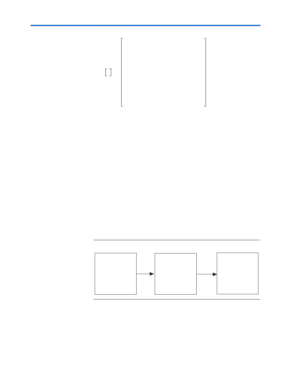
Figure 7–34 shows the different stages.
Figure 7–34. Three Separate Stages in Implementing the 2-D DCT
Because the row processing and column processing blocks share the same
1-D 8-point DCT algorithm, the hardware implementation shows this
block as being shared. The DCT algorithm requires a serial-to-parallel
conversion block at the input because it works on blocks of eight data
C
10000000
0C
4
000000
00C
6
C–
2
0000
00C
2
C
6
0000
0000C
7
C–
5
C
3
C–
1
0000C
5
C–
1
C
7
C
3
0000C
3
C–
7
C–
1
C–
5
0000C
1
C
3
C
5
C
7
=
C
x
πx
16
------cos=
Row
processing
Column
processing
Transpose
matrix