Altera Corporation 7–57
September 2004 Stratix Device Handbook, Volume 2
Implementing High Performance DSP Functions in Stratix & Stratix GX Devices
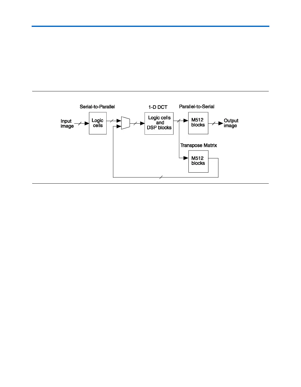
points in parallel. There is also a parallel-to-serial conversion block at the
output because the column processing stage generates the output image
column-by-column. In order to have the output in the same order as the
input (i.e., row-by-row), this conversion is necessary. Appropriate scaling
needs to be applied to the completed transform but this can be combined
with the quantization stage which often follows a DCT [1]. Figure 7–35
shows a top-level block diagram of this design.
Figure 7–35. Block Diagram on Serial Implementation of 2-D DCT
The implementation of the 1-D DCT block is based on the algorithm
shown in Figure 7–33. The simple addition and subtraction operations in
stages 1, 2 and 3 are implemented using logic cells. The multiply and
multiply-addition operations in stage 4 are implemented using DSP
blocks in the Stratix device in the simple multiplier mode, two-multiplier
adder mode, and the four-multiplier adder mode. An example of the
multiply-addition block is shown in Figure 7–36.