7–58 Altera Corporation
Stratix Device Handbook, Volume 2 September 2004
Discrete Cosine Transform (DCT)
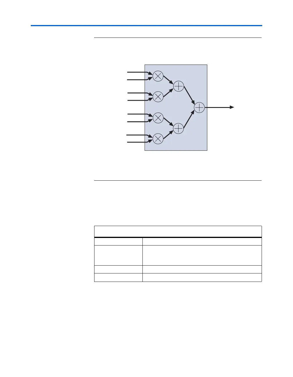
Figure 7–36. Details on the Implementation of the Multiply-Addition Operation
in Stage 4 of the 1-D DCT Algorithm
Note to Figure 7–36:
(1) Referring to Figure 7–33. S3
n
is an output from stage 3 of the DCT and C
mn
is a
matrix coefficient. C
x
=cos (xπ/16).
DCT Implementation Results
Table 7–18 shows the results of implementing a 2-D DCT with 18-bit
precision, as shown in Figure 7–35.
DCT Design Example
Download the 2-D convolutional filter (d_dct.zip) design example from
the Design Examples section of the Altera web site at www.altera.com.
Table 7–18. 2-D DCT Implementation Results
Part EP1S20F780
Utilization Lcell: 1717/18460 (9%)
DSP Block 9-bit element: 18/80 (22%)
Memory bits: 2816/1669248 (<1%)
Performance 165 MHz
Latency 80 clock cycles
DSP Block - Four-Multipliers Adder Mode (18-bit)
C
m1
C
m2
C
m3
C
m4
S3
1
y
k
S3
4
S3
3
S3
2