8–12 Altera Corporation
Stratix Device Handbook, Volume 2 July 2005
Interfaces
Table 8–4 lists the AC timing specifications for the PCS transmitter.
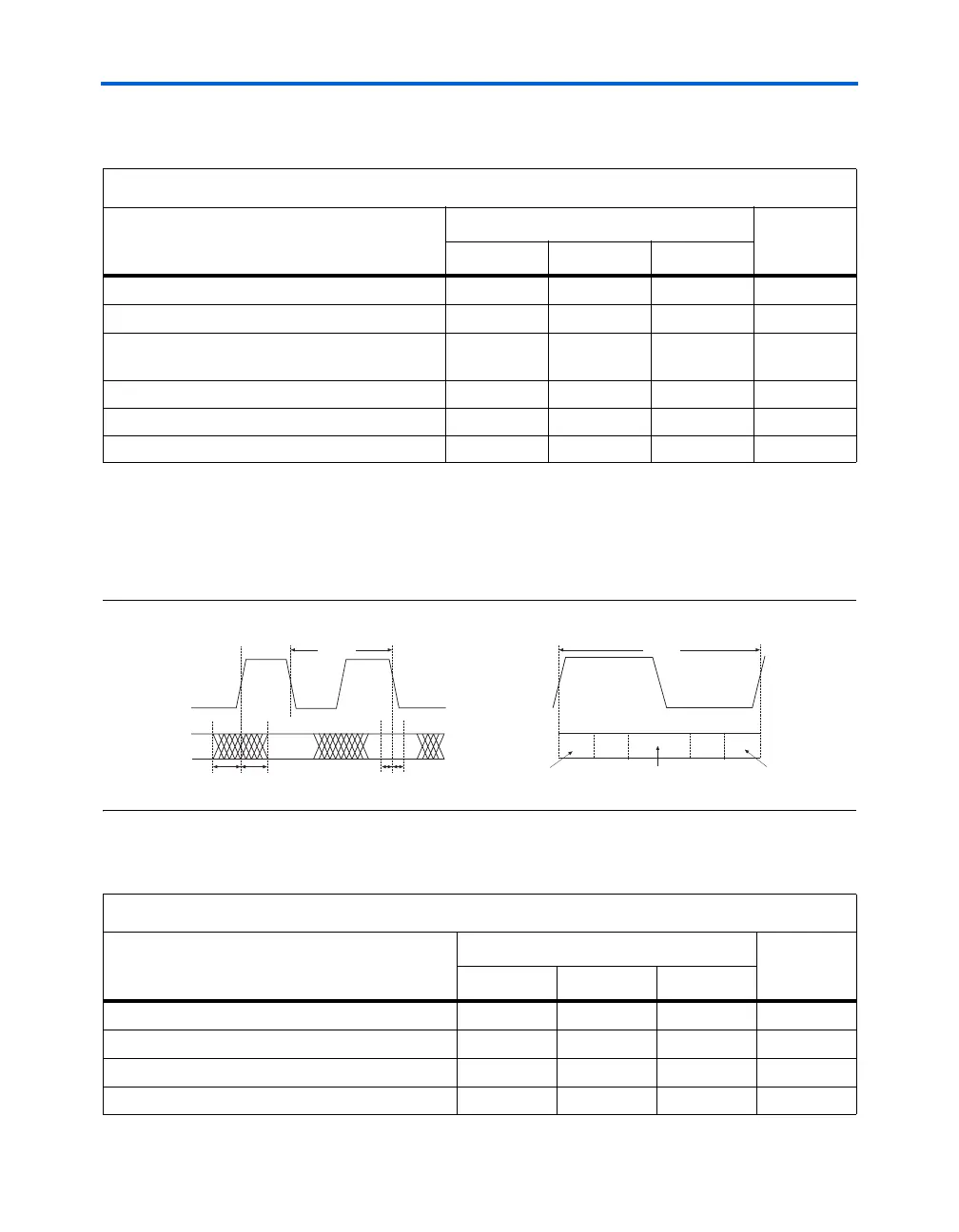
Figure 8–9 shows the AC timing diagram for the Stratix and Stratix GX
PCS receiver interface. You can determine the PCS sampling window by
adding T
setup
to T
hold
. Receiver skew margin (RSKM) refers to the amount
of skew tolerated on the printed circuit board (PCB).
Figure 8–9. PCS Receiver Timing Diagram
Table 8–5 lists the AC timing specifications for the PCS receiver interface.
Table 8–4. PCS Transmitter Timing Specifications
Parameter
Value
Unit
Min Typ Max
PMA_TX_CLK T
period
(WAN)
1,608 ps
PMA_TX_CLK T
period
(LAN)
1,552 ps
Data invalid window before the rising edge
(T
cq_pre
)
200 ps
Data invalid window after the rising edge (T
cq_post
) 200 ps
PMA_TX_CLK duty cycle
40 60 %
PCS transmitter channel-to-channel skew 200 ps
T
period
T
cq_pre
T
cq_post
T
setup
T
hold
Valid
Data
RX_DATA[15..0]
RSKM
Sampling Window
RSKM
Transmitter Channel-to-Channel
Skew/2
Transmitter Channel-to-Channel
Skew/2
T
period
RX_DATA[15..0]
PMA_RX_CLK
PMA_RX_CLK
Table 8–5. PCS Receiver Timing Specifications (Part 1 of 2)
Parameter
Value
Unit
Min Typ Max
PMA_RX_CLK T
period
(WAN)
1,608 ps
PMA_RX_CLK T
period
(LAN)
1,552 ps
Data invalid window before the rising edge (T
cq_pre
)200ps
Data invalid window after the rising edge (T
cq_post
)200ps