10–6 Altera Corporation
Stratix Device Handbook, Volume 2 July 2005
General Architecture
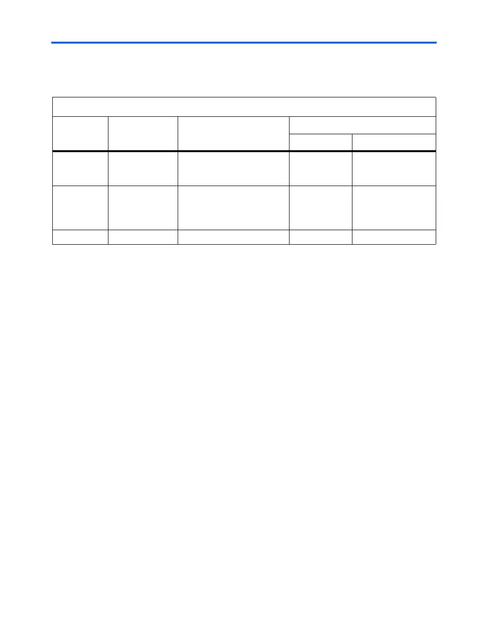
Table 10–3 highlights the new location syntax used for Stratix and
Stratix GX devices.
Use the following guidelines with the new naming system:
■ The anchor point, or origin, in Stratix and Stratix GX devices is in the
bottom-left corner, instead of the top-left corner as in APEX II and
APEX 20K devices.
■ The anchor point, or origin, of a large block element (e.g., a M-RAM
or DSP block) is also the bottom-left corner.
■ All numbers are zero-based, meaning the origin at the bottom-left of
the device is X0, Y0.
■ The I/O pins constitute the first and last rows and columns in the
X-Y coordinates. Therefore, the bottom row of pins resides in
X<number>, Y0, and the first left column of pins resides in X0,
Y<number>.
■ The sub-location of elements, N, numbering begins at the top.
Therefore, the LEs in an LAB are still numbered from top to bottom,
but start at zero.
Figure 10–2 show the Stratix and Stratix GX architectural element
numbering convention. Figure 10–3 displays the floorplan view in the
Quartus II software.
Table 10–3. Stratix & Stratix GX Location Assignment Syntax
Architectural
Elements
Element Name Location Syntax
Example of Location Syntax
Location Description
Blocks
LAB, DSP,
DSPOUT, M512,
M4K, M-RAM
<element_name>_X<number>
_Y<number>
LAB_X1_Y1
Designates the LAB in
row 1, column 1
Logic
LE, IOC, PLL,
DSPMULT,
SERDESTX,
SERDESRX
<element_name>_X<number>
_Y<number>_N<number>
LC_X1_Y1_N0
Designates the first
LE, N0, in the LAB
located in row 1,
column 1
Pins (1) I/O pins
pin_<pin_label> pin_5
Pin 5
Note to Table 10–3:
(1) You can make assignments to I/O pads using IOC_X<number>_Y<number>_N<number>.