Altera Corporation 11–13
July 2005 Stratix Device Handbook, Volume 2
Configuring Stratix & Stratix GX Devices
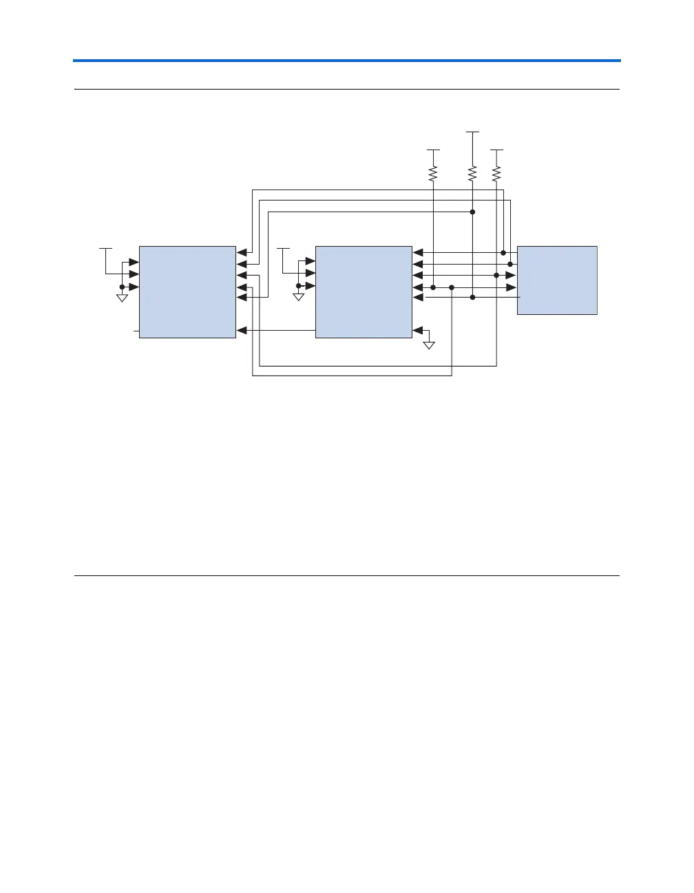
Figure 11–4. Configuring Multiple Stratix & Stratix GX Devices with A Single Configuration Device Note (1)
Notes to Figure 11–4:
(1) When performing multi-device active serial configuration, you must generate the configuration device programmer
object file (.pof) from each project’s SOF. You can combine multiple SOFs using the Quartus II software through the
Device & Pin Option dialog box. For more information on how to create configuration and programming files, see
the Software Settings section in the Configuration Handbook, Volume 2.
(2) The pull-up resistor should be connected to the same supply voltage as the configuration device.
(3) The enhanced configuration devices and EPC2 devices have internal programmable pull-ups on OE and nCS. You
should only use the internal pull-ups of the configuration device if the nSTATUS and CONF_DONE signals are pulled
up to 3.3 V or 2.5 V (not 1.8 V or 1.5 V). If external pull-ups are used, they should be 10 kΩ.
(4) EPC16, EPC8, and EPC4 configuration devices cannot be cascaded.
(5) The nINIT_CONF pin is available on EPC16, EPC8, EPC4, and EPC2 devices. If nINIT_CONF is not used, nCONFIG
must be pulled to V
CC
through a resistor. The nINIT_CONF pin has an internal pull-up resistor that is always active
in EPC16, EPC8, EPC4, and EPC2 devices. These devices do not need an external pull-up resistor on the
nINIT_CONF pin.
Configuration
Device (4)
DCLK
DATA
OE
nCS
nINIT_CONF (5)
DCLK
DATA0
nSTATUS
CONF_DONE
nCONFIG
V
CC
V
CC
GND
nCE
V
CC
DCLK
DATA0
nSTATUS
CONF_DONE
nCONFIG
GND
nCE
MSEL2
MSEL1
nCEO
nCASC
(2)
(2)
(2)
nCEO
N.C.
Stratix or Stratix GX Device 2
Stratix or Stratix GX Device 1
MSEL0
V
CC
GND
MSEL2
MSEL1
MSEL0
V
CC
(3)
10 kΩ 10 kΩ