11–14 Altera Corporation
Stratix Device Handbook, Volume 2 July 2005
Configuration Schemes
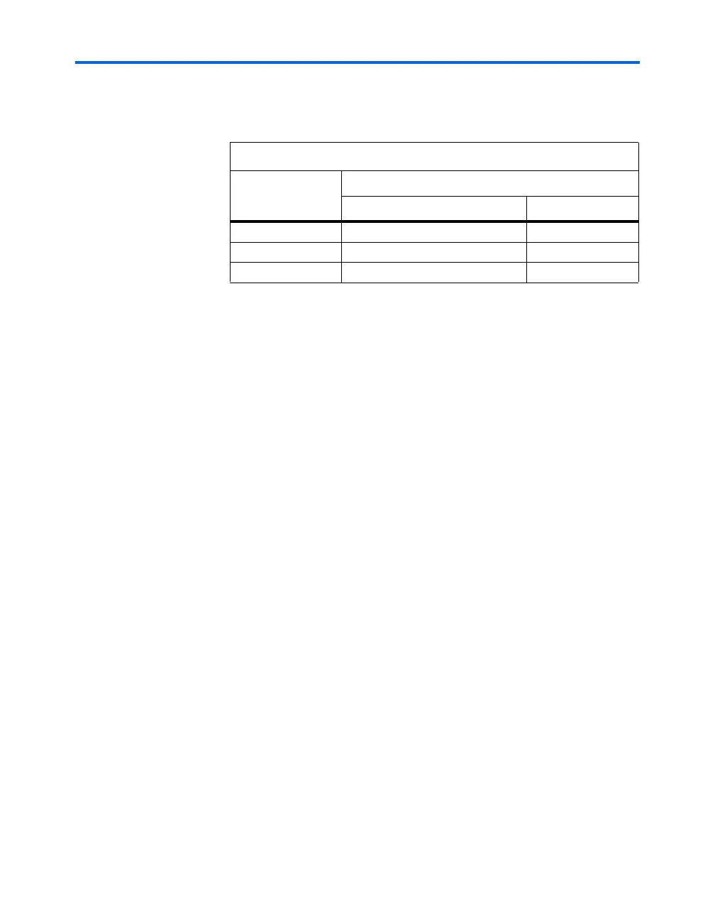
Table 11–7 shows the status of the device DATA pins during and after
configuration.
PS Configuration with a Download Cable
In PS configuration with a download cable, an intelligent host transfers
data from a storage device to the Stratix or Stratix GX device through the
MasterBlaster, USB-Blaster, ByteBlaster II or ByteBlasterMV cable. To
initiate configuration in this scheme, the download cable generates a
low-to-high transition on the nCONFIG pin. The programming hardware
then places the configuration data one bit at a time on the device’s DATA0
pin. The data is clocked into the target device until CONF_DONE goes high.
The CONF_DONE pin must have an external 10-kΩ pull-up resistor in
order for the device to initialize.
When using programming hardware for the Stratix or Stratix GX device,
turning on the Auto-Restart Configuration on Frame Error option does
not affect the configuration cycle because the Quartus II software must
restart configuration when an error occurs. Additionally, the Enable
User-Supplied Start-Up Clock (CLKUSR) option has no affect on the
device initialization since this option is disabled in the SOF when
programming the FPGA using the Quartus II software programmer and
a download cable. Therefore, if you turn on the CLKUSR option, you do
not need to provide a clock on CLKUSR when you are configuring the
FPGA with the Quartus II programmer and a download cable.
Figure 11–5 shows PS configuration for the Stratix or Stratix GX device
using a MasterBlaster, USB-Blaster, ByteBLaster II or ByteBlasterMV
cable.
Table 11–7. DATA Pin Status Before & After Configuration
Pins
Stratix or Stratix GX Device
During After
DATA0 (1)
Used for configuration User defined
DATA[7..1] (2)
Used in some configuration modes User defined
I/O Pins Tri-state User defined
Notes to Ta b le 11 – 7:
(1) The status shown is for configuration with a configuration device.
(2) The function of these pins depends upon the settings specified in the Quartus II
software using the Device & Pin Option dialog box (see the Software Settings
section in the Configuration Handbook, Volume 2, and the Quartus II Help software
for more information).