Altera Corporation 11–27
July 2005 Stratix Device Handbook, Volume 2
Configuring Stratix & Stratix GX Devices
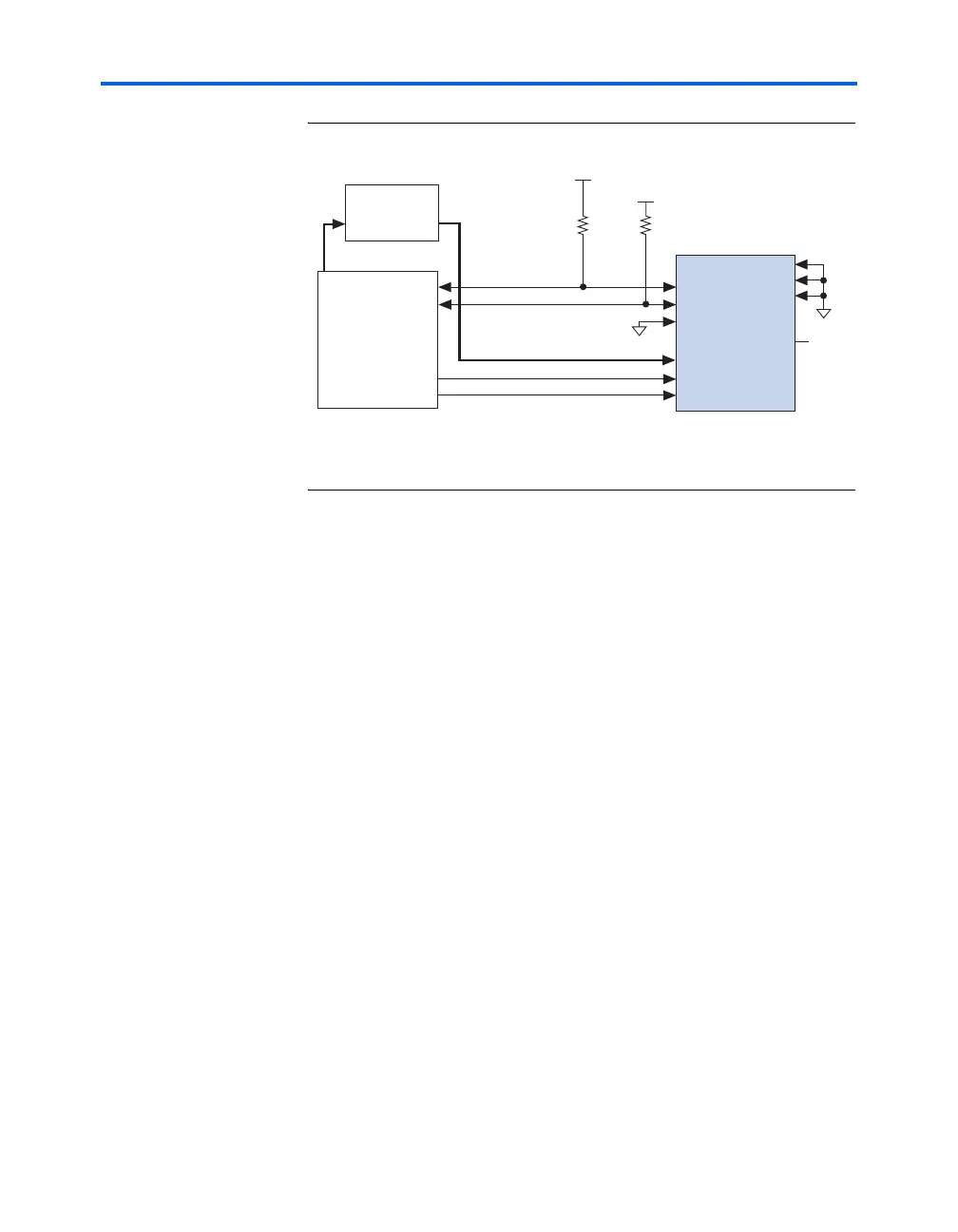
Figure 11–12. Parallel Configuration Using a Microprocessor
Note to Figure 11–12:
(1) The pull-up resistors should be connected to any V
CC
that meets the Stratix high-
level input voltage (V
IH
) specification.
For multi-device parallel configuration with a microprocessor, the nCEO
pin of the first Stratix or Stratix GX device is cascaded to the second
device’s nCE pin. The second device in the chain begins configuration
within one clock cycle; therefore, the transfer of data destinations is
transparent to the microprocessor. Because the CONF_DONE pins of the
devices are connected together, all devices initialize and enter user mode
at the same time.
Because the nSTATUS pins are also tied together, if any of the devices
detects an error, the entire chain halts configuration and drives nSTATUS
low. The microprocessor can then pulse nCONFIG low to restart
configuration. If the Auto-restart configuration after error option is on,
the Stratix and Stratix GX devices release nSTATUS after a reset time-out
period. The microprocessor can then reconfigure the devices once
nSTATUS is released. Figure 11–13 shows multi-device configuration
using a microprocessor. Figure 11–14 shows multi-device configuration
when both Stratix and Stratix GX devices are receiving the same data. In
this case, the microprocessor sends the data to both devices
simultaneously, and the devices configure simultaneously.
Microprocessor
CONF_DONE
nSTATUS
nCE
DATA[7..0]
nCONFIG
Stratix Device
Memory
ADDR DATA[7..0]
GND
MSEL1
MSEL2
V
CC
(1)
V
CC
(1)
GND
DCLK
nCEO
N.C.
MSEL0
10 kΩ10 kΩ