11–28 Altera Corporation
Stratix Device Handbook, Volume 2 July 2005
Configuration Schemes
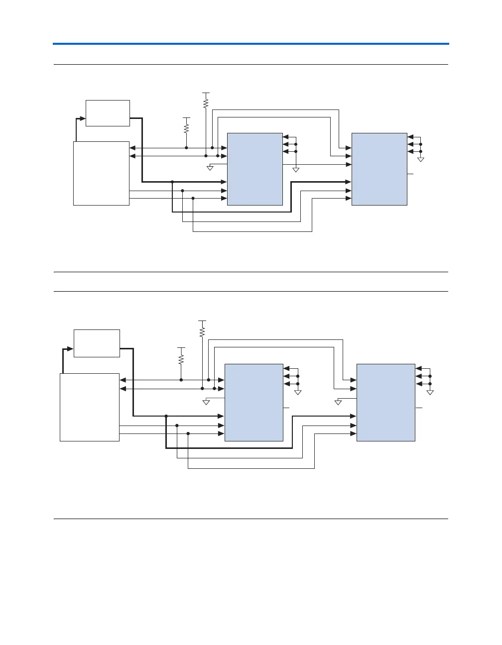
Figure 11–13. Parallel Data Transfer in Serial Configuration with a Microprocessor
Note to Figure 11–13:
(1) You should connect the pull-up resistors to any V
CC
that meets the Stratix high-level input voltage (V
IH
)
specification.
Figure 11–14. Multiple Device Parallel Configuration with the Same Data Using a Microprocessor
Notes to Figure 11–14:
(1) You should connect the pull-up resistors to any V
CC
that meets the Stratix high-level input voltage (V
IH
)
specification.
(2) The nCEO pins are left unconnected when configuring the same data into multiple Stratix or Stratix GX devices.
f For more information on configuring multiple Altera devices in the same
configuration chain, see the Configuring Mixed Altera FPGA Chains
chapter in the Configuration Handbook, Volume 2.
Microprocessor
CONF_DONE
nSTATUS
nCE
DATA[7..0]
nCONFIG
Stratix Device
Memory
ADDR DATA[7..0]
GND
V
CC
(1)
V
CC
(1)
DCLK
nCEO
CONF_DONE
nSTATUS
nCE
DATA[7..0]
nCONFIG
Stratix Device
MSEL1
MSEL2
DCLK
nCEO
N.C.
GND
MSEL0
MSEL1
MSEL2
MSEL0
GND
10 kΩ
10 kΩ
Microprocessor
CONF_DONE
nSTATUS
nCE
DATA[7..0]
nCONFIG
Stratix Device
Memory
ADDR DATA[7..0]
GND
V
CC
(1)
V
CC
(1)
DCLK
CONF_DONE
nSTATUS
nCE
DATA[7..0]
nCONFIG
Stratix Device
MSEL1
MSEL2
DCLK
nCEO
N.C.
(2)
GND
MSEL0
MSEL1
MSEL2
GND
MSEL0
nCEO
N.C.
(2)
GND
10 kΩ
10 kΩ