Altera Corporation 11–29
July 2005 Stratix Device Handbook, Volume 2
Configuring Stratix & Stratix GX Devices
FPP Configuration Timing
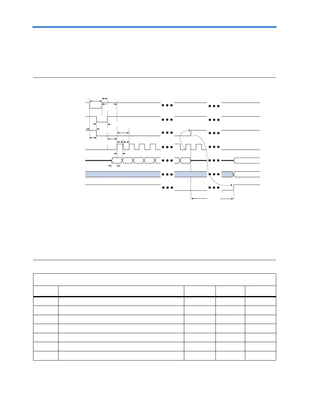
Figure 11–15 shows FPP timing waveforms for configuring a Stratix or
Stratix GX device in FPP mode. Table 11–9 shows the FPP timing
parameters for Stratix or Stratix GX devices.
Figure 11–15. Timing Waveform for Configuring Devices in FPP Mode Note (1)
Notes to Figure 11–15:
(1) The beginning of this waveform shows the device in user-mode. In user-mode, nCONFIG, nSTATUS, and
CONF_DONE are at logic high levels. When nCONFIG is pulled low, a reconfiguration cycle begins.
(2) Upon power-up, the Stratix II device holds nSTATUS low for the time of the POR delay.
(3) Upon power-up, before and during configuration, CONF_DONE is low.
(4) DCLK should not be left floating after configuration. It should be driven high or low, whichever is convenient.
DATA[] is available as user I/Os after configuration and the state of these pins depends on the dual-purpose pin
settings.
Table 11–9. FPP Timing Parameters for Stratix & Stratix GX Devices (Part 1 of 2)
Symbol Parameter Min Max Units
t
CF2CK
nCONFIG high to first rising edge on DCLK
40 µs
t
DSU
Data setup time before rising edge on DCLK
7ns
t
DH
Data hold time after rising edge on DCLK
0ns
t
CFG
nCONFIG low pulse width
40 µs
t
CH
DCLK high time
4ns
t
CL
DCLK low time
4ns
t
CLK
DCLK period
10 ns
nCONFIG
nSTATUS (2)
CONF_DONE (3)
DCLK
DATA[7..0}
User I/O
INIT_DONE
Byte 0 Byte 1 Byte 2 Byte 3 Byte n
t
CD2UM
t
CF2ST1
t
CF2CD
t
CFG
t
CH
t
CL
t
DH
t
DSU
t
CF2CK
t
STATUS
t
CLK
t
CF2ST0
t
ST2CK
High-Z
User Mode
(4)
(4)
User Mode