Altera Corporation 11–33
July 2005 Stratix Device Handbook, Volume 2
Configuring Stratix & Stratix GX Devices
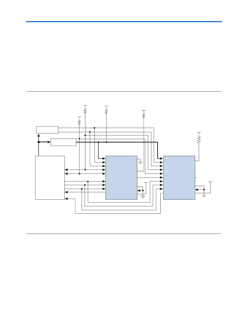
You can also use PPA mode to configure multiple Stratix and Stratix GX
devices. Multi-device PPA configuration is similar to single-device PPA
configuration, except that the Stratix and Stratix GX devices are cascaded.
After you configure the first Stratix or Stratix GX device, nCEO is asserted,
which asserts the nCE pin on the second device, initiating configuration.
Because the second Stratix or Stratix GX device begins configuration
within one write cycle of the first device, the transfer of data destinations
is transparent to the microprocessor. All Stratix and Stratix GX device
CONF_DONE pins are tied together; therefore, all devices initialize and
enter user mode at the same time. See Figure 11–17.
Figure 11–17. PPA Multi-Device Configuration Circuit
Notes to Figure 11–17:
(1) If not used, you can connect the CS pin to V
CC
directly. If not used, the nCS pin can be connected to GND directly.
(2) Connect the pull-up resistor to the same supply voltage as the Stratix or Stratix GX device.
GND
Address Decoder
ADDR
ADDR
Memory
DATA[7..0]
nCS
CS
(1)
CONF_DONE
nSTATUS
nCE
nWS
nRS
nCONFIG
RDYnBSY
nCS
CS
(1)
CONF_DONE
nSTATUS
nCE
nWS
nRS
nCONFIG
RDYnBSY
Microprocessor
DATA[7..0]
DATA[7..0]
nCEO
N.C.
nCEO
(2)
(3)
DCLK
(2)
DCLK
(2)
10 kΩ
10 kΩ
10 kΩ
10 kΩ
Stratix Device 1 Stratix Device 2
MSEL2
MSEL1
MSEL0
V
CC
GND
V
CC
GND
V
CC
V
CC
V
CC
V
CC
(2)
10 kΩ
V
CC
MSEL2
MSEL1
MSEL0