Altera Corporation 1–55
July 2005 Stratix Device Handbook, Volume 2
General-Purpose PLLs in Stratix & Stratix GX Devices
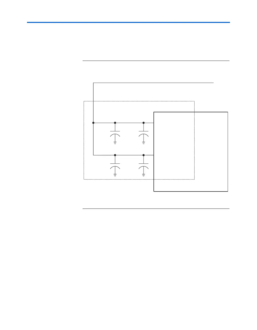
Filter each isolated power pin with a decoupling circuit shown in
Figure 1–26. Decouple the isolated power pins with a 0.1-μF and a
0.001-μF parallel combination of ceramic capacitors located as close as
possible to the Stratix device.
Figure 1–26. Stratix PLL External Clock Output Power Ball Connections
Note (1)
Note to Figure 1–26:
(1) Figure 1–26 also applies to VCC_PLL6_OUTA/B.
VCC_PLL5_OUTA
V
CCIO
Supply
Stratix Device
VCC_PLL5_OUTB
0.1 μF 0.001 μF
0.1 μF 0.001 μF