2–6 Altera Corporation
Stratix Device Handbook, Volume 2 July 2005
TriMatrix Memory
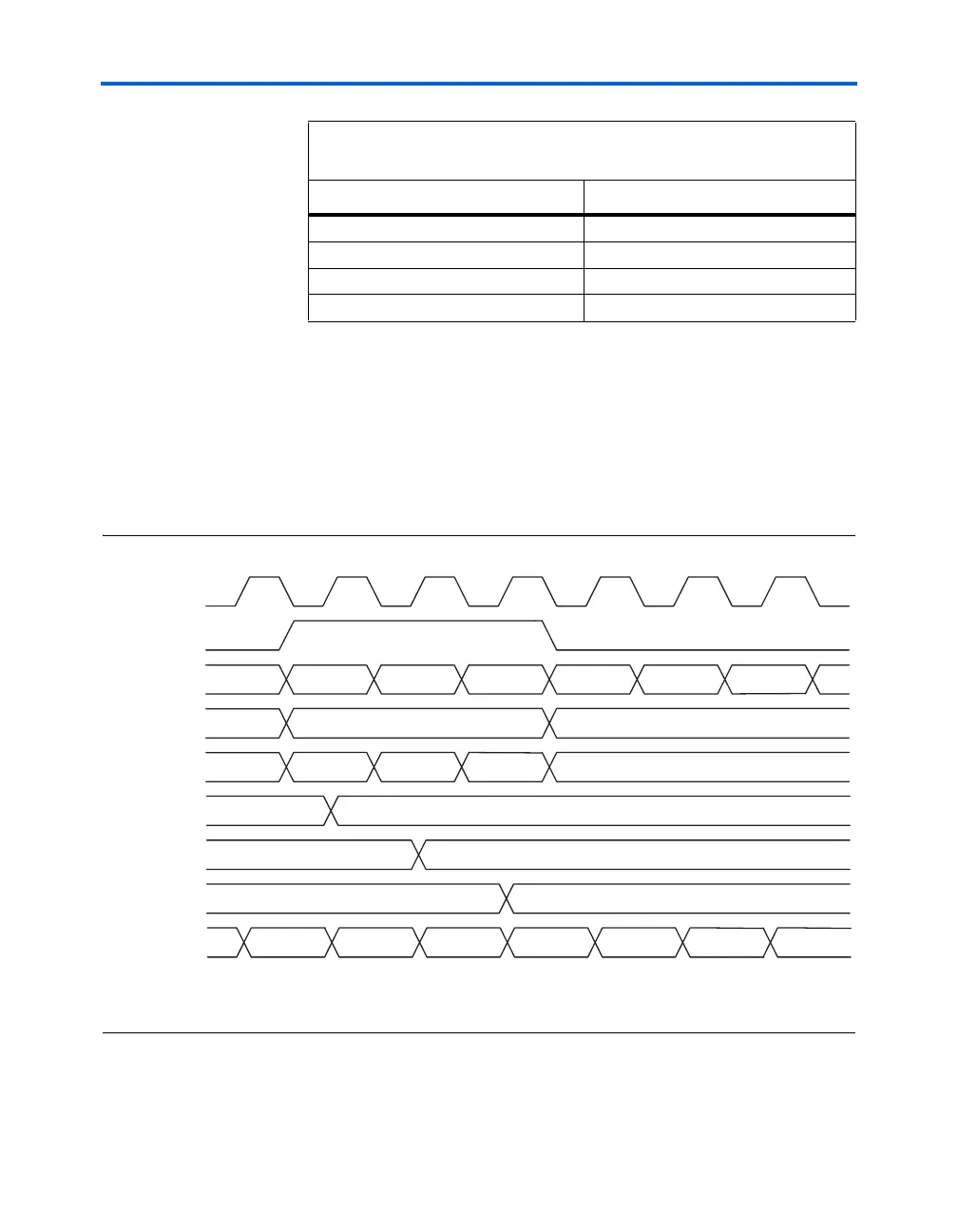
Byte Enable Functional Waveform
Figure 2–1 shows how both the wren and the byteena signals control
the write operations of the RAM.
Figure 2–1. Byte Enable Functional Waveform Note (1)
Note to Figure 2–1:
(1) For more information on simulation output when a read-during-write occurs at the same address location, see
“Read-During-Write Operation at the Same Address” on page 2–25.
[12] = 1 [116..108]
[13] = 1 [125..117]
[14] = 1 [134..126]
[15] = 1 [143..135]
Notes to Ta b le 2 – 6 :
(1) Any combination of byte enables is possible.
(2) Byte enables can be used in the same manner with 8-bit words, i.e., in × 16, × 32,
× 64, and × 128 modes.
Table 2–6. M-RAM Combined Byte Selection for × 144 Mode (Part 2 of 2),
Notes (1), (2)
byteena_a datain × 144
inclock
wren
address
data_in
asynch_data_out
an
XXXX
a0 a1 a2 a0 a1 a2
doutn
ABXX
XXCD
ABCD ABFF FFCD
ABCD
byteena
XX
10 01
11
XXXX
XX
ABCD
ABCDFFFF
FFFF
FFFF
ABFF
FFCD
contents at a0
contents at a1
contents at a2