2. Technical System Description 1/2010 2 - 47
BA-TE-DE08C M.KAY
Dialog+ SW9xx_sm_Chapter 2_1-2010.doc/pdf <100329> yymmdd
B. Braun Avitum AG
Dialog
+
SW 9.xx
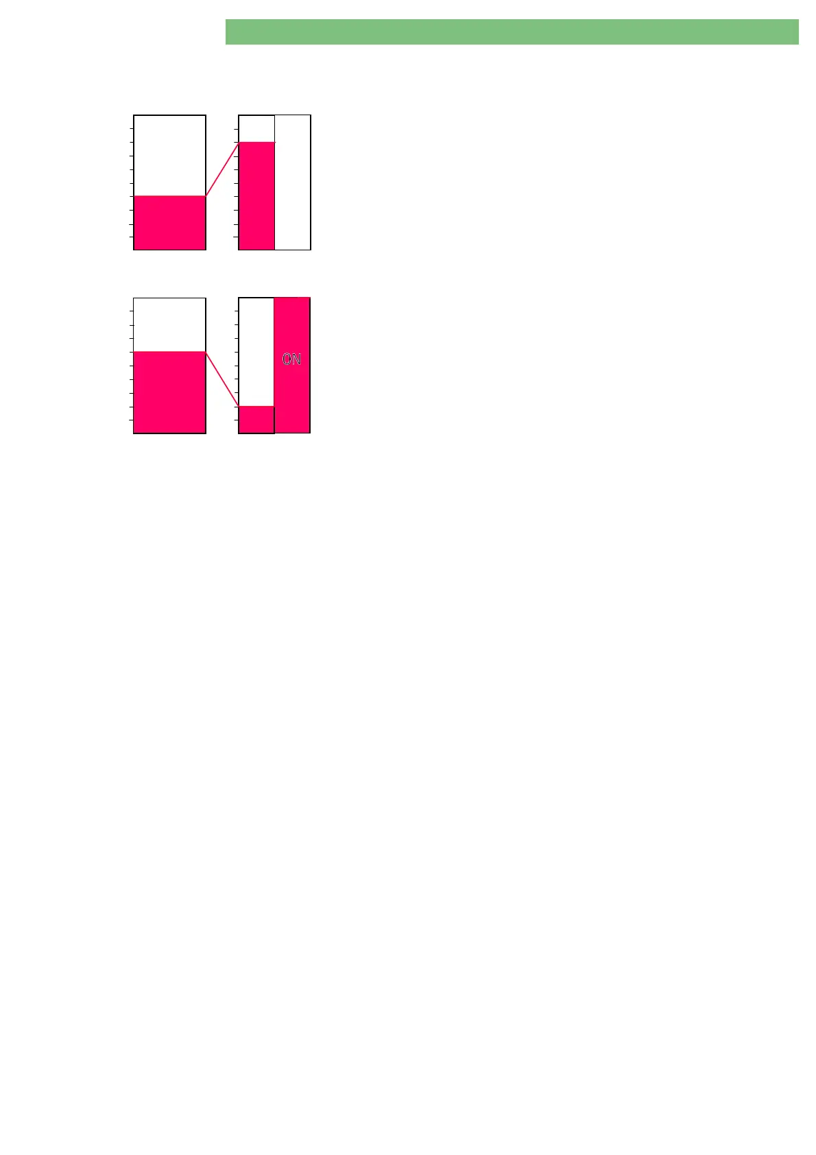
Double-Stage Heater and
Microcontroller
The SMPS-MC controls the double-stage heater
H1
/
H2
(2 x 900 W). The first
heater circuit (heater
H1
, 900 W) is driven in 2 % steps. The second heater
H2
is switched with max. power (900 W) if 50% of
H1
is reached.
H1
is then
controlled with half-wave-shapes, generated by the microcontroller
D900
from
the SMPS-MC.
Example:
Set value of LLC = 40 % (based on 1800 W)
•
H1 = 80 % (based on 900 W)
•
H2 = switched off permanently
Set value of LLC = 60 % (based on 1800 W)
•
H1 = 20 % (based on 900 W)
•
H2 = switched on permanently
The microcontroller converts the predefined heater power from LLC into bit
patterns (1 bit corresponds to a mains voltage half cycle) to control both
heaters.
Hardware Watchdog
(see also LED H900)
The hardware watchdog
HW-WD
switches the SMPS-MC in a safe condition if
the microcontroller fails, i.e. the buzzer is activated, the heater and both
voltages +24VGB/+24 VGD are switched off. The staff call is activated if
present.
LED H900 Operating Status 3 Modes:
LED off : Microcontroller is not working
LED flashes with 5 ... 10 Hz: Microcontroller has detected an error
LED flashes with approx. 2 Hz: Microcontroller is working correctly
24 V Outputs
The 24 V of the main converter supplies the following circuits:
•
24 VL via fuse F600
•
24 VGB via fuse F601 and relay K3
•
24 VGD via fuse F602 and Relay K4
Battery Management
The SMPS-MC has a battery management, with the following components:
•
Screw terminal XP3.1 (+) and XP3.2 (-) for batteries
•
Protection against incorrect polarity
•
Electronic connection
•
Deep discharge protection TES
•
Charging current regulator
•
Battery full detection
•
Shut-down circuit for the battery test
•
Enable signal
AKKU_EN
All output voltages are maintained during a power failure if the signal
AKKU_EN
was set prior to the power failure. The secondary auxiliary voltage is
also present. The battery is charged if mains voltage is present. The charging is
performed via a body diode even without
AKKU_EN
. A comparator protects the
battery from deep discharge by disconnecting the battery source from the
circuit at a voltage < 22 V
±
0.5 V via a MOSFETT switch.
+5 V Voltage
The 5 V DC/DC converter generates the 5 V voltage from the 24 V. The
overvoltage protection circuit (crowbar) is triggered at 5.75 V
±
250 mV. A reset
of the overvoltage protection circuit is possible only by switching the machine
off and on again. The soldered fuse F300 disconnects the 24 V in case of a short
circuit in the DC/DC converter.
+12 V Voltage
A DC/DC converter generates the –12 V voltage from the 24 V. The soldered
fuse F500 disconnects the 24 V in case of a short circuit in the DC/DC
converter.
H1 H2
1800W
720W = 720W
900W900W
20
20
4040
80
80
60
60
%
%
LLC 40%
80%
OFF
H1 H2
1800W
1080W = 180W + 900W
(>900W: H2 = ON)
900W900W
20
20
40
40
80 80
60
60
%
%
LLC 60%
20%