Brooks Automation 6. Operation
Part Number: 605914 Rev. B Water Cooling Systems
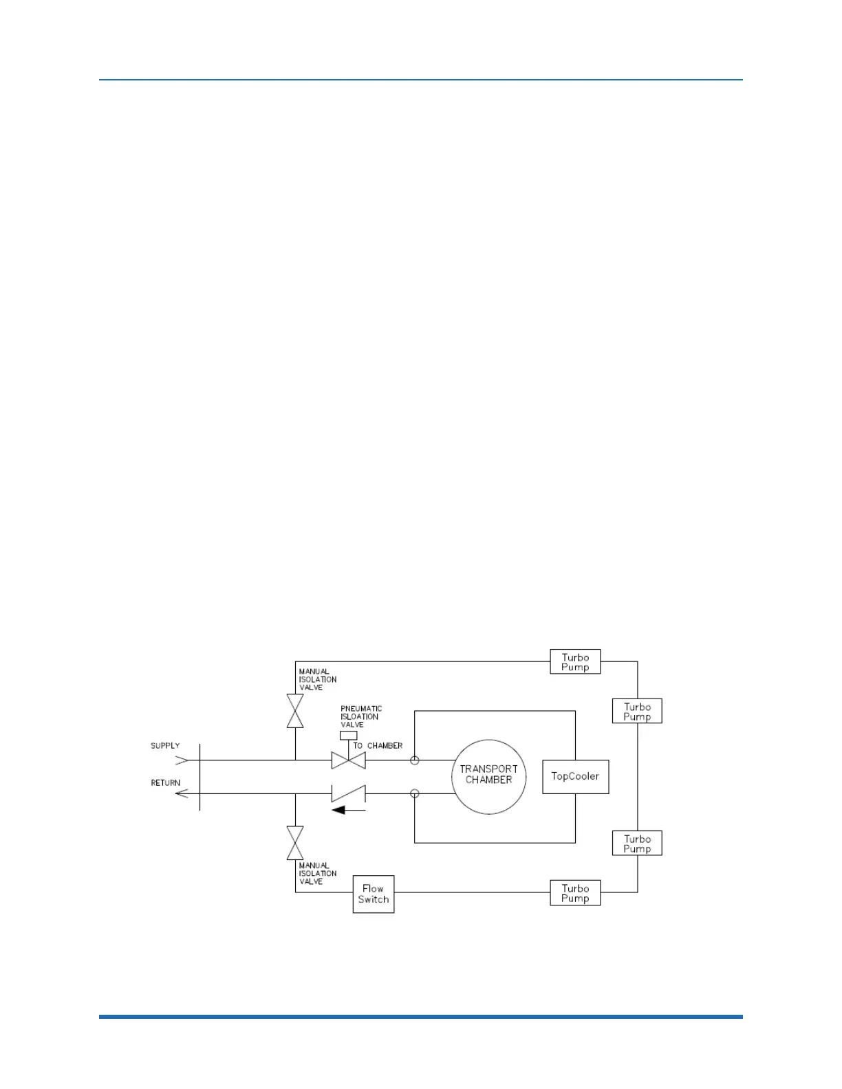
Chamber Cooling System
Thiscoolingsystemisusedintherapidcool-downprocessofthechamberandlidafterchamber
heating.Watercoolingisalsousedforthepumpsandisrunthroughthesamewatercoolingsystem
asshowninFigure6-12.
IftheElectricHeateroptionisused,thecoolingflowtotheTransportChamber(TC)iscontrolled
withaseparatepneumaticallycontrolledisolationvalve.Thisvalvewillbeopenduringnormal
operationstopreventstagnationandminimizecorrosionwithinthecoolingchannel.FlowtotheTC
willstoponlyduringtheheatingportionofthechamberbakeoutcycle.
Pump Cooling System
AFlowSwitchismountedonthesystemcoolingoutletintheturbopumpcoolinglooptoassurethat
coolinglossdoesnotoccurbecauseofpoorfluidflowwithintheMXsystem’scoolingsystem.The
trippointissetbythemanufacturertodetectlossofcoolingflowtocriticalheatloads.TheFlow
Switchwillprovideawarningtotheoperator.Thiscoolingloopalsocontainstwomanualisolation
valvesformaintenance.
Wafer Cooling System
WafercoolingisavailableasanoptionusingtheTopCooler.Wafersmustbecooledifthe
temperatureofthewaferishotenoughtomelttheplasticcassettesintheLoadLocks.Innormal
operation,unprocessedwafersareplacedonthePoppetShelf,hewaferisthenloweredontothe
wafersupportsontheCoolPlaten.Duringtheventcyclenitrogen,orothergas,conductsheatfrom
thewafertotheplaten.Referto"TopCoolerOperation"onpage135fordetailedinformation.
Figure 6-12: Water Cooling Diagram - Chamber, Pumps, TopCooler
Copyright © 2023, Brooks Automation, Inc.
133