Brooks Automation 3. Installation
Part Number: 605914 Rev. B Installation Procedure
NOTE: Itmaybeconvenienttomountthesecomponentsafterinitialinstallationand
testing.
Step Action
1.
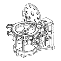
RemovetheblankoffsfromthevacuumfacetsoftheMarathonExpressVacuumBackEnd.
2.
AdjusttheProcessModulesothatitsMaterialTransportPlaneisat1100mm(refertotheProcess
Module’sUserManual).EnsurethattheProcessModuleremainslevelwhilemakinganyadjustments
totheheight.
3.
MatetheProcessModuletothevacuumfacetoftheMarathonExpressbyinsertingthepinsonthe
ProcessModuleintotheholesontheVacuumSlotValveofthefacet.
NOTE: Itmaybenecessarytore-adjusttheheightofthemodule(s)toalignthemtotheTransport
Chamber.Ifaheightre-adjustmentisrequired,takecaretoensurethatthemoduleremainslevel.
4.
OncetheProcessModuleismated,clamptheflangesoftheProcessModuleandtheSlotValve
togetherusingtheISOclampsprovided.
Intermodule Connections
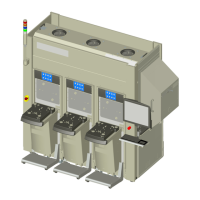
ThestandardconfigurationoftheMarathonExpressdoesnotrequireanyconnectionsbemade
betweentheMarathonExpressVacuumTransportSystemandtheVCEmodulesduring
installation.
MostcablesintheMarathonExpressareshippedfromthefactoryalreadyconnectedtothetool.
However,individualsubsystemssuchasanyrackmountablecomponentsmustbeconnected
duringinstallation.SeeFigure1-1onpage13forallBrookscomponentsintheMXsystem.
Wiring,vacuum,andventsystemdiagramsforthespecificsystemconfigurationaresuppliedwith
thismanual.Refertothesediagramswhileinstallingthesystemtoverifycorrectconnections.The
configurationoftheMarathonExpresswilldeterminewhichcomponentsmaybeincludedwiththe
system.Usethefollowinginstructionsasareferenceforsteporderonly.Someconnectionsmay
havebeeninstalledatthefactory,inthiscaseonlyverificationoftheconnectionisrequired.
RackMountableBrooksAutomationComponentConnections
Ensureallconnectionsareroutedsuchthattheywillnotbedamagedandthattheydonotpresenta
hazardtopersonnel.
Copyright © 2023, Brooks Automation, Inc.
67