Brooks Automation 3. Installation
Part Number: 605914 Rev. B Installation Procedure
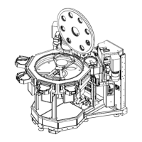
LoadLockConnections
Step Action
1.
SignalcablesfromeachLoadLock:
LoadLockNodeJ4 toTurboPumpController(optional)
LoadLockNodeJ5 toIonGauge
LoadLockNodeJ6 toConvectronGauge
LoadLockNodeJ7 toSubstrateSensorontheTransportChamber
LoadLockNodeJ8 toIsolationValve
LoadLockNodeJ9 toAtmosphericSwitch
LoadLockNodeJ10 toSlotValveontheTransportChamber
LoadLockNodeP11 toI/ODistributionHubJ17 for A-Lock, J12 for B-Lock
LoadLockNodeJ12 toPneumaticManifoldP1
2.
ConnectpneumaticlinesfromLoadLock:
RefertothePneumatic,Vacuum,andVentDiagramssuppliedwiththismanualforcolorand
terminationofalllines.
ProcessModuleConnections
Step Action
1.
FromtheProcessModulesto(J5)FacetNodePMinterface.
NOTE: IfaprocessmoduleWILLNOTbeconnectedtoaFacetNode,ajumper
connectorlabeledPDP(suppliedwiththesystem)attheJ5connectormustbe
installed.
Facilities Connections
ThestandardconfigurationoftheMarathonExpressrequirescompressedair,nitrogen(ventgas),
vacuum,exhaust,electricalpower,communicationsconnections,andoptionallycoolingwater,
waterreturn,andargon(coolgas).Refertothe"FacilitiesSpecifications"onpage21fordetailed
descriptionsoftherequireduser-suppliedfacilities.
AllMarathonExpressClusterToolIntegrationPlatformscomewiththerequiredconnectorsto
facilitateinterfacingthesystem,alongwithconnectorsforthevacuumsources.TheMXsystemis
suppliedwithFacilitiesandInterfacePanelslocatedasshowninFigure3-5,andFigure3-6.Allthe
connectorsonthefacilitiesinterfacesarelabeledforeasyidentification.
Copyright © 2023, Brooks Automation, Inc.
69