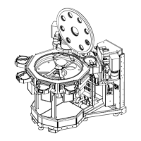
3. Installation Marathon Express
Installation Procedure Part Number: 605914 Rev. B
Step Action
1.
Signalcablesfromthehostcontrollertosystem:
DIG0OUTPUTS FROM 0 TO 15toI/ODistributionHubJ16
DIG0OUTPUTS FROM 16 TO 31toI/ODistributionHubJ13
DIG1OUTPUTS FROM 0 TO 15toI/ODistributionHubJ8
DIG1OUTPUTS FROM 16 TO 31toI/ODistributionHubJ19
DIG2OUTPUTS (Optional)toI/ODistributionHubJ10
NetworkconnectiontoSerialCommunicationsModuleJ1
NOTE: Ifanyoftheaboveoptionsarenotinstalled,theprotectivecapsshouldbeplacedoverthe
exposedconnector.
2.
FromtheDCPowerSupplytotheMainDCHarnessP.DC.LFlocatedinthelowerfacilities.
3.
FromtheHeaterPowerSupply(Optional),MainHeatercableP.HPfromHeaterPowerSupplytoMain
HeaterHarnessJ.HH.LF
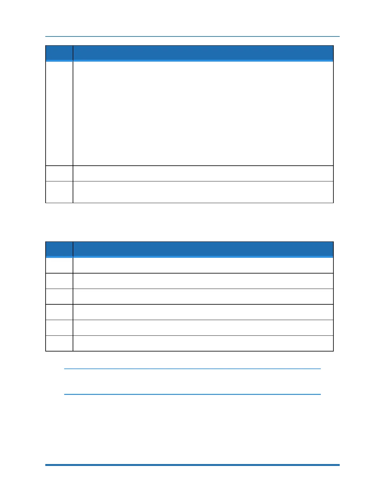
RackMountableVacuumCommunicationConnections
Step Action
1.
FromWaterPumpControllertoTransportChamberWaterPumpREMOTE
2.
FromCryoPumpControllertoTransportChamberCryopump
3.
FromTurboPumpControllertoTurboPumpB-Lock
4.
FromTurboPumpControllertoTurboPumpA-Lock
5.
FromTurboPumpControllertoTurboPumpTransportChamber
6.
FromoptionalTurboPumpControllertosecondTurboPumpTransportChamber
NOTE: Donotconnectfacilitiespoweratthistime.Facilitiespowerwillbeconnected
afterallotherconnectionshavebeenmade.
68
Copyright © 2023, Brooks Automation, Inc.