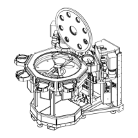
Brooks Automation 8. System Alignment
Part Number: 605914 Rev. B Vacuum Cassette Elevator Configuration and Alignment
Step Action
12.
RepeatforeachLoadLock.
Inordertoreducetheoverallverticalheighttheplatformmusttravel,thisalignmentprocedurehas
establishedtheHomeposition0.500inchbelowthecenterlineofthebottom-mostslot.Toposition
theplatformforproperoperationwithdifferentcassettetypes,theappropriateoffsetforthecassette
typebeingusedintheelevatormustbeentered.RefertotheVCEUserManualforappropriateCTO
values.
Set the Load Lock T and R Coordinates
Theexactrotationalaxis(T)andradialaxis(R)coordinatesofeachLoadLockmustbetaughttothe
robot.Thisprocedureconsistsofrotatingandextendingtherobotarmuntiltheendeffectoris
positionedoverthecenteroftheLoadLockelevatorplatformandthenstoringthispositioninthe
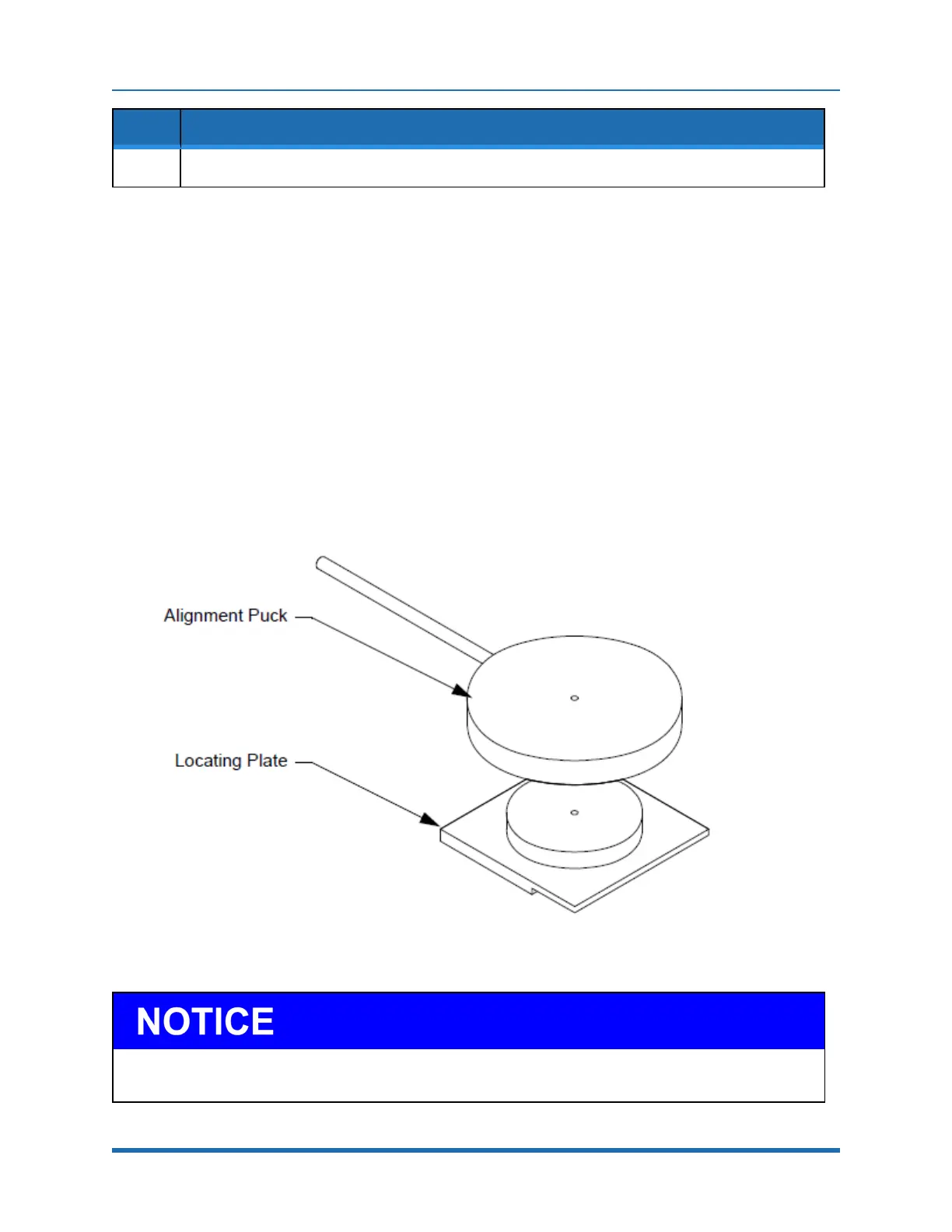
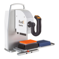
robotmemory.TheMarathonExpresscomeswithatwo-partRobot/VCEAlignmentFixtureforthe
specifiedendeffector,showninFigure8-4,tofacilitatethisprocedure.
Figure 8-4: Robot/VCE Alignment Fixture
Donot“home”theelevatorwhiletherobot’sarmsorendeffectorareextendedintotheLoadLock’schamberas
severedamagetotheelevatororrobotmayresult.
Copyright © 2023, Brooks Automation, Inc.
163