8. System Alignment Marathon Express
Vacuum Cassette Elevator Configuration
and Alignment
Part Number: 605914 Rev. B
Step Action
3.
SelecttheappropriateCassetteTypeOffset(CTO)configurationvaluefromtheBrooksAutomation
VCEUserManualandenteritusingtheSetCassetteTypeOffsetcommand,refertotheCommand
ReferenceintheVCEUserManual.
00, S, CF, CT, cto
NOTE: TheCTOisusuallysetatBrookswithrequesteddimensionscalculatedbythecassettesize.
BeforeresettingtheCTO,requestthevaluefirstandthenchangeonlyifnecessary.
4.
CommandtheVCEtoSlot1.
00, A, GO, 1
5.
RaisetheendeffectortotheUP(WTP)position.
6.
Extend(jog)therobot’sendeffectorintotheLoadLockandovertheplatform.
7.
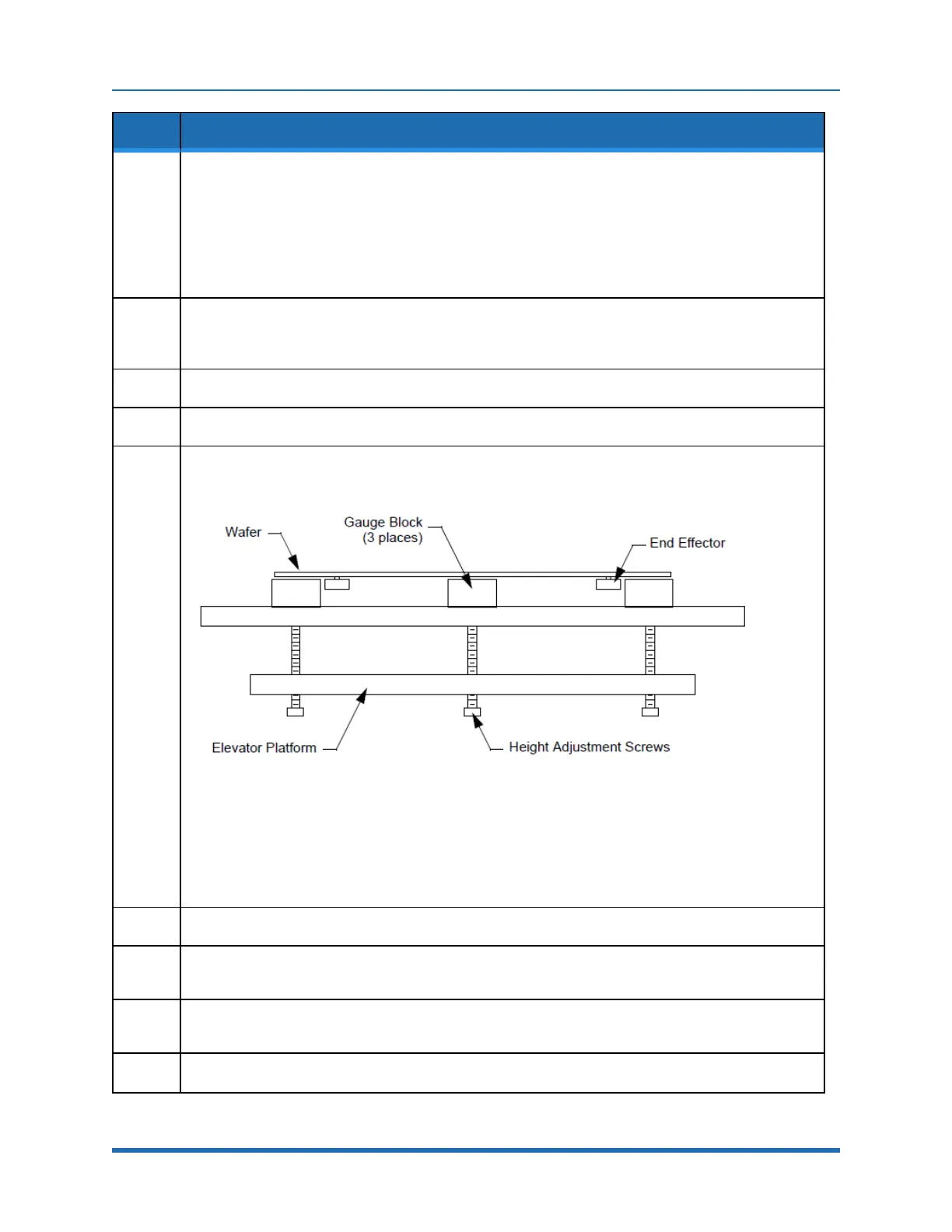
Locatethespring-loadedheight-adjustmentscrewsbeneaththeplatform,showninFigure8-3,and
placethreegaugeblocksontheplatformovertheheight-adjustmentscrews.RefertotheVCE
alignmentproceduresintheVCEUserManualorusethefollowinginstructions:
Figure 8-3: Platform Height Adjustment Screws
Forwafersupto150mmwafers,placethegaugeblocksontheplatformwiththe0.535inchdimension
orientedvertically.
For200mmwafers,placethegaugeblocksontheplatformwiththe0.985inchdimensionoriented
vertically.
8.
Placeanappropriatesizedwaferontotherobot’sendeffector.
9.
Sightingalongthebottomsurfaceofthewafer,adjusttheplatformheightadjustmentscrewsuntilthe
topsofthegaugeblocksjusttouchthebottomsurfaceofthewafer.
10.
Sightcarefullyalongtheendeffectortoinsurethatthewaferhasnotbeenliftedoffthesurface(moving
thegaugeblockshouldnotcausethewafertomove).
11.
Removethewaferandthegaugeblocksandretracttheendeffector.
162
Copyright © 2023, Brooks Automation, Inc.