Brooks Automation 6. Operation
Part Number: 605914 Rev. B System Operation Overview
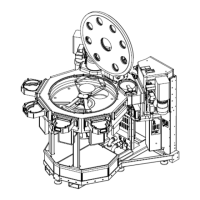
Robot’s Frame of Reference
ThetypicalframeofreferencefortheTransportChamberisdefinedbytherobot’scoordinate
system.ThetopviewshowninFigure6-2isahorizontalx-yplane,andeachpositionwithinthis
planeisdefinedusingapolarcoordinatenotationforeachrobot.Lookingatthetopviewofthe
system,therobot’srotational,orT(theta),positionvalueincreasesfrom0°attheHomepositionto
360°inaclockwisedirection.Therobot’sradial,orR,axisismeasuredfromthecenter-lineofthe
robotradiallyoutwardinmillimeters.
NOTE: Thesystem’s0°axisisdefinedbytherobot’s0°position,whichistypicallythe
robot’srotationalHomeposition.
Thethirdaxisintherobot’sFrameofReferenceisthevertical,orZ,axis.ThezeropositionfortheZ-
axisisdefinedbytherobot’sverticalHomeposition.
Aligner’s Frame of Reference
AnotherframeofreferencethatisusedwithintheMarathonExpressVacuumTransportSystemis
thealigner’sFrameofReference.Thealignerisinstalledonallsystemsrequiringprecisionmaterial
placement.Whenawaferisplacedintothealigner,thealignerreportsboththemagnitudeandthe
directionofthewaferseccentricity.Thesevaluesareexpressedaspolarcoordinatesbasedonthe
aligner’sinternalframeofreference.
Thealigner’sFrameofReferencehasitsoriginatthealigner’scenterofrotationwithits0°axis
definedasthelinebetweenthecenterofthealignerandthecenteroftheCCDarray,asshownin
Figure6-2.Lookingatthetopviewofthealigner,thealignerwillreportarotational,orT(theta),
positionvaluetoindicatethedirectionofthewafer’seccentricity,whichincreasesfrom0°ina
clockwisedirection.Thealigner’sradial,orR,axisismeasuredfromthecenter-lineofthealigner
radiallyoutwardinmillimetersandisusedtodescribetheamountofthewafer’seccentricity.
Thealigner’sFrameofReferencecanbeadjustedtobringitintolinewiththerobotasshownin
Figure6-2byusingtheCCDPOScommand.
TheTandReccentricityvaluesobtainedbythealigneraresenttothesystemcontroller,whichthen
commandstherobottoexecutea“DeltaPick”ofthewafer.Thedeltapickperformedbytherobotis
basedonthewafereccentricityvaluesobtainedbythealigner,whichthesystemcontrollerthen
usestocalculateanewRandTpositionforthealigner.ThenewlycalculatedRandTvaluesforthe
alignerareonlyusedonce(duringthe“Pick”ofthewafer),whichresultsinthewaferbeingcentered
ontherobot’sendeffector.
System Operation Overview
ThematerialtransferoperationoftheMarathonExpressconsistsofthecommunicationbetween
theVCEloadlocks,therobot,andthevacuumalignerintheMarathonExpresssystemandthehost
controller.Thedetailedoperationofthesecomponentsisdescribedintheirrespectiveuser
Copyright © 2023, Brooks Automation, Inc.
111