8. System Alignment Marathon Express
Vacuum Cassette Elevator Configuration
and Alignment
Part Number: 605914 Rev. B
Step Action
1.
VerifythatallelevatorparametersaresetcorrectlybyusingthecommandsdescribedintheVCEUser
Manual.
2.
Ensurethattherobot’sarmisretractedandtheelevatordoorisclosed,thenmovetheelevatorplat-
formtoslot1.
3.
UsingtheCDM,movetherobottotheinitialLoadLockT-axispositionusingtheMovetoStationcom-
mand.Refertotherobotmanual.
4.
EnterthehandlocatecommandontheCDM.Thiscommandwillcausetherobotservostorelease,
allowingmanualpositioningoftheendeffector.
5.
PlacetheLocatingPlateontheplatformsothatitlocksintoplace.PlacetheAlignmentPuckonthe
LocatingPlatewiththehandlepointingoutandensurethatitcanturnfreelyonthefixture.
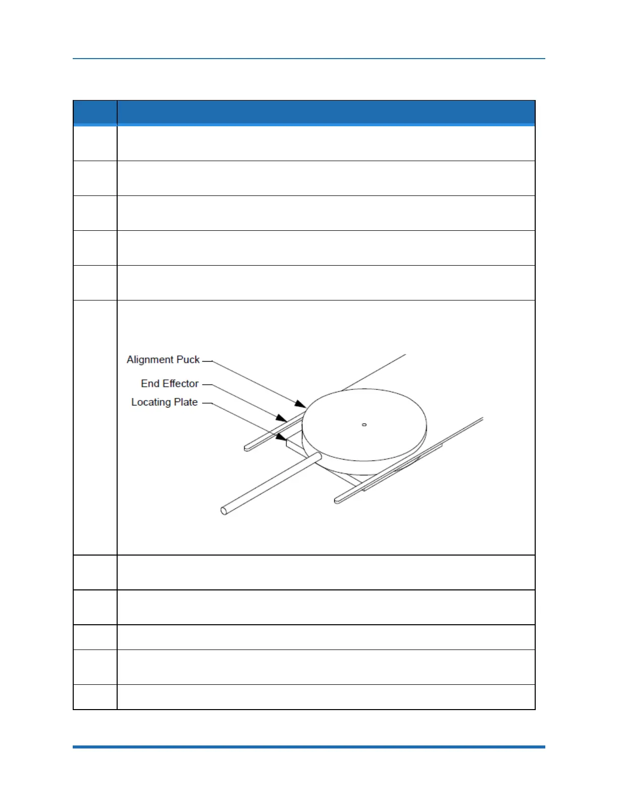
6.
Manuallypositiontherobot’sendeffectoruntiltheU-shapedslotfitsaroundtheAlignmentPuckas
showninFigure8-3andthebottomofthe“U”iscloseto,butnottouching,thepuck(approximately
+.002inch).
Figure 8-5: Centering End Effector On Alignment Fixture
7.
OncetheendeffectorisproperlylocatedaroundthePuck,usetheCDMtoviewandrecordtheR
(radial)andT(rotational)axislocationsforthisstation.
8.
UsingtheCDM,storetheRandTaxislocations.Also,recordtheRandTvaluesintheappropriate
worksheetprovidedinAppendixC:"StationIdentification"onpage221.
9.
Retracttherobot’sarmandremovetheAlignmentPuckandLocatingPlatefromtheplatform.
10.
RecordtheStationcoordinatesintheappropriateworksheetprovidedinAppendixC:"StationIden-
tification"onpage221.
11.
RepeatforeachLoadLock.
164
Copyright © 2023, Brooks Automation, Inc.