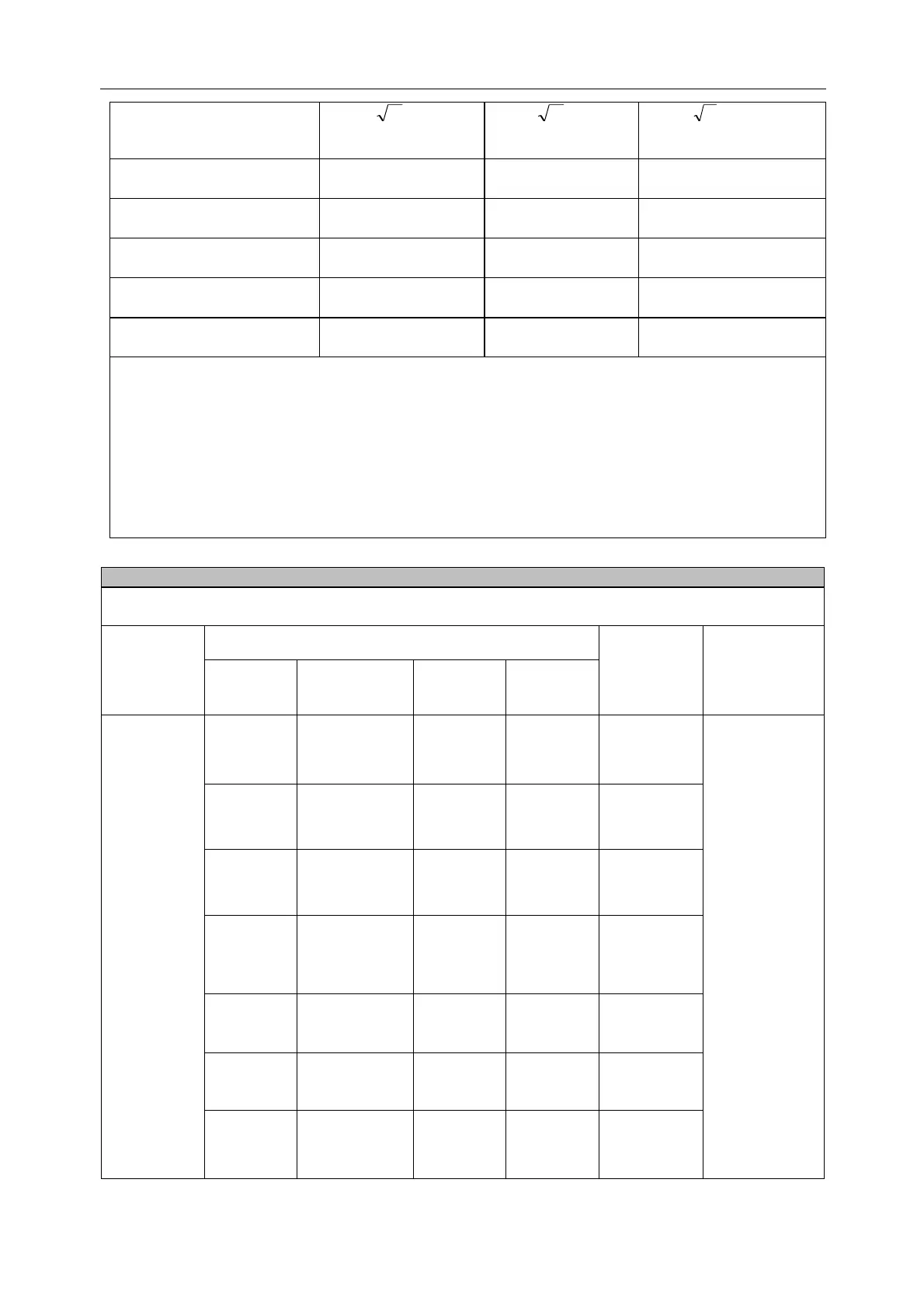
In case of any maximum rated output power other than listed above, use the formula (“
P
” refers to the
transmitter’s maximum rated output power (W) learnt from the transmitter manufacturer) in the relevant
transmitter frequency column to calculate the recommended isolation distance “d” (m).
Frequencies of portable and mobile transmitters for which the recommended separation distance is 30 cm (12
inches)
Note 1: At 80 MHz and 800 MHz, the higher frequency band was applied.
Note 2: These guidelines may not apply to all situations. Electromagnetic propagation is affected by absorption
and reflection from structures, objects and people.
Declaration - IMMUNITY to proximity fields from RF wireless communications equipment
The monitors are intended for use in an electromagnetic environment in which RF wireless communications
equipment are controlled.
Electromagnetic
environment -
guidance
Radiated RF
IEC 61000-4-
3
*FM+ 5Hz
deviation: 1kHz
sine
**Pulse
Modulation:
217Hz
1720 MHz
1845 MHz
1970 MHz
**Pulse
Modulation:
217Hz
**Pulse
Modulation:
217Hz
5240 MHz
5500 MHz
5785 MHz
**Pulse
Modulation:
217Hz