5.5.3 Watchlist Window
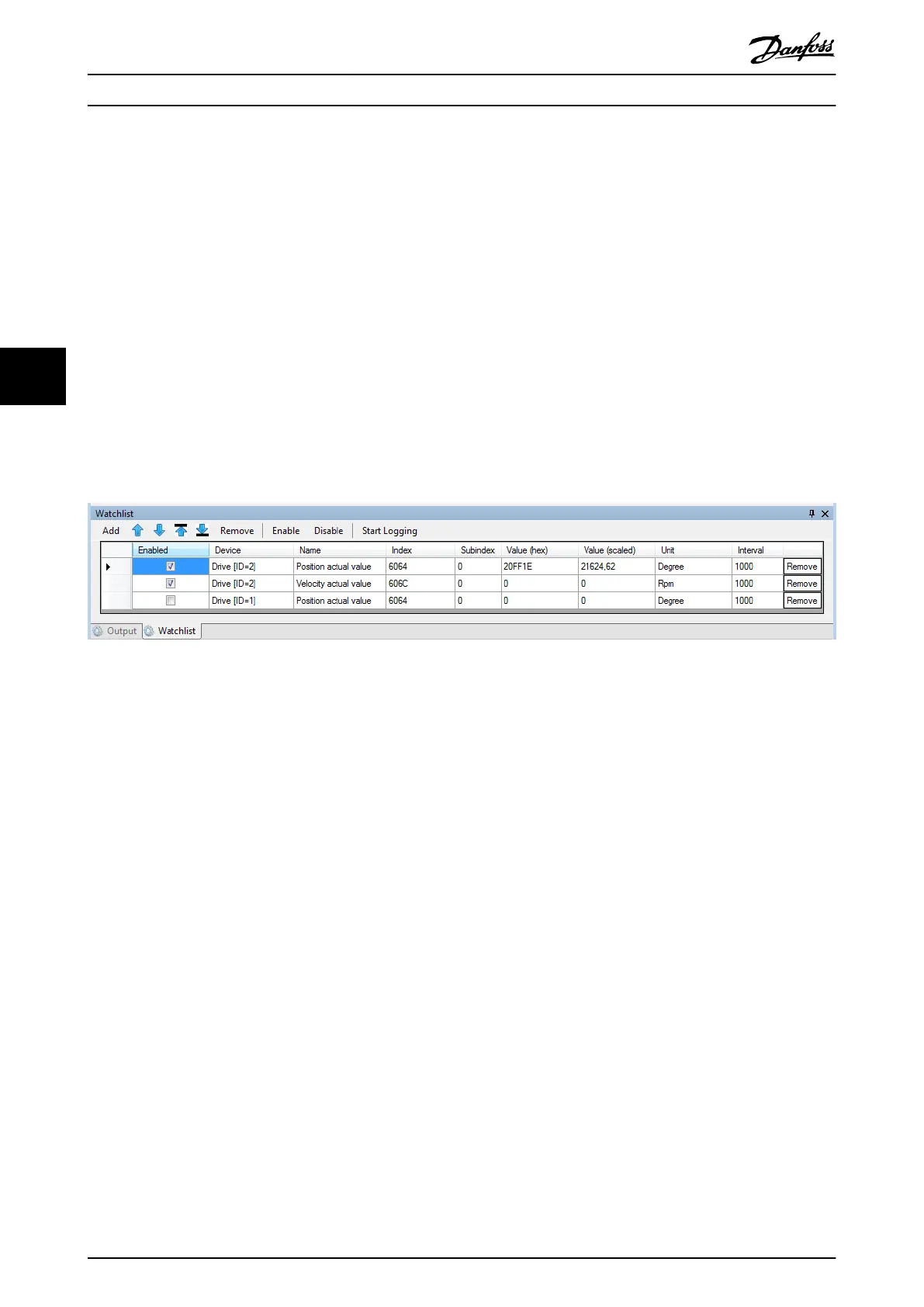
Parameters that are added to the Watchlist window are continuously polled from the device using a specied read interval.
All readable parameters of all congured devices can be used in the Watchlist window. All writable parameters can also be
changed in the Watchlist window by writing the value into 1 of the columns Value (hex) or Value (scaled).
To log the cyclically read values in a text le, click on the Start Logging button and then select the target log le path. The
log le has a plain-text comma-separated format (.csv) and can be viewed without the need of any specialized software.
The Interval for polling the values are
congurable individually for each parameter in multiples of the Watchlist resolution
parameterized in the Options window (see chapter 5.5.8 Options Window).
The parameters can be added and moved up or down the list. It is also possible to remove, enable, or disable the update of
each individual parameter and remove, enable, or disable all parameters of a
specic device. Furthermore, it is possible to
remove, enable, or disable all the parameters in the Watchlist.
The Watchlist window can be hidden or shown via menu [Window → Show/Hide watchlist], or by pressing the [F5] key.
Illustration 5.12 Watchlist Window
5.5.4 Output Window
The Output window shows operating information, warnings, and errors from the Toolbox application itself, as well as
warnings and errors from the connected devices. It shows detailed information regarding Toolbox failures, incorrect congu-
rations, or missing software components and supports the following functions:
•
Analysis of communication
•
Tracking device states
•
Searching for errors
•
Testing and debugging devices
The maximum number of messages can be set by using the Options window (see chapter 5.5.8 Options Window). The Output
window logging level has 3 possible settings that can be changed using the Options window:
•
High: Shows basic events.
•
Medium: Default setting.
•
Low: Shows detailed communication and conguration events.
When a new message is shown, the Output window automatically scrolls to the bottom of the list in order to show the
latest message.
The Output list entries are
classied as Messages, Warnings, or Errors. Select whether an entry type should be shown by
checking/unchecking the respective checkbox at the top of the Output window.
The timestamp of the message is generated when the message is shown. The content of the window can be saved to a
plain-text le by clicking on the Save log button.
Operation with ISD Toolbox
VLT
®
Integrated Servo Drive ISD
®
510 System
118 Danfoss A/S © 01/2017 All rights reserved. MG36D102
55

 Loading...


