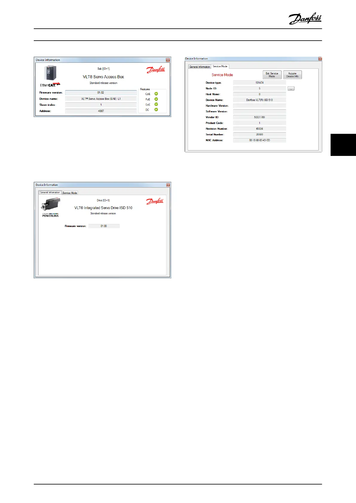
Illustration 5.9 Device Information Window – EtherCAT
®
For Ethernet POWERLINK
®
The Device Information window for Ethernet POWERLINK
®
devices contains the
rmware version of the device and
contains 2 tabs: General Information and Service Mode.
The General Information tab is shown in Illustration 5.10.
Illustration 5.10 Information Window – Ethernet POWERLINK
®
– General Information
The Service Mode tab contains controls for entering the
Ethernet POWERLINK
®
specic service mode of the ISD 510
devices (servo drive and SAB), and for reading device
information in Service Mode. Illustration 5.11 shows the
Service Mode tab page of the Device Information window.
To enter Service Mode, the device must be connected using
direct, acyclic communication. First carry out a power cycle
if the device has been connected to a PLC.
Clicking on the button Enter Service Mode changes the
device state to service mode and enables the button
Acquire Device Info. When clicking on the Acquire Device
Info button, the device information is read from the device.
While the device is in Service Mode, it is not possible to
close the Device Information window or access any other
control in the ISD Toolbox. This ensures the integrity of the
device state.
Illustration 5.11 shows the Service Mode tab page of the
Device Information window. The device is in service mode
(indicated by the red text “Service Mode”), and the device
information shown in the respective text boxes has already
been read.
Illustration 5.11 Information Window – Ethernet POWERLINK
®
– Service Mode
The Service Mode tab consists of the following read-only
text
elds that are read when entering Service Mode and
acquiring the device information:
•
Device type
•
Node ID
•
Host Name
•
Device Name
•
Hardware Version
•
Software Version
•
Vendor ID
•
Product Code
•
Revision Number
•
Serial Number
•
MAC Address
While the device is in Service Mode, the Node ID can be
changed by clicking on the button on the right of the
Node ID
eld and typing in the desired node ID in the
pop-up window. The ID is instantly applied on the device
and a power cycle is not required.
Operation with ISD Toolbox Programming Guide
MG36D102 Danfoss A/S © 01/2017 All rights reserved. 117
5 5

 Loading...


