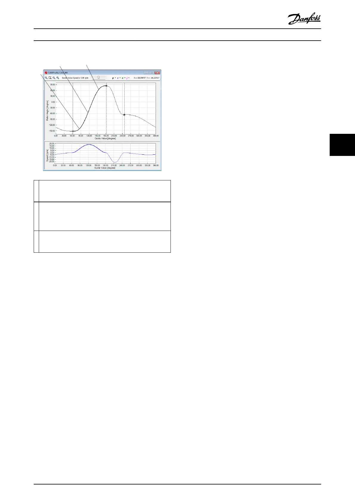
1 By dragging the left side of the segment (near to its
preceding guide node), only the start position of the segment
is changed.
2 By dragging the center of the segment, both the start
position and the end position of the segment are changed
and the segment is thus moved up or down.
3 By dragging the right side of the segment (near to its
succeeding guide node), only the end position of the segment
is changed.
Illustration 5.73 Graphically Editing a Guide Poly
Move Distance segment
The Move Distance segment has the following properties:
•
Parameters
- Start position: Species the axis position
at the beginning of the segment,
relative to the end position of the
previous segment. If the parameter is
left blank (unspecied), the logical CAM
position from the previous segment is
used as the starting position.
•
Start
- Start acceleration: Species the
acceleration of the axis at the beginning
of the segment. It is the same as the
start acceleration of Guide poly.
- Start velocity: Species the velocity of
the axis at the beginning of the
segment. It is the same as the start
velocity of Guide poly.
•
End
- End acceleration: Species the
acceleration at the end of the segment.
For more information, see Start
acceleration.
- End velocity: Species the velocity at
the end of the segment. For more
information, see Start velocity.
When the position of the preceding node or succeeding
node of a move distance segment is changed (graphically
or numerically), the segment is automatically recalculated
and redrawn.
When any of the move distance segment properties are
changed by using the Property Window, the segment is
automatically recalculated and redrawn.
The move distance segment is calculated with the aid of
the Simulated angle property. This can be used for testing
the result of dierent angles sent to the drive. The default
value is 0°.
The start position or simulated angle property values
cannot be edited graphically. Use the Property Window to
change them.
Return segment
The Return segment has the following properties:
•
Parameters
- Start position: Species the axis position
at the beginning of the segment,
relative to the end position of the
previous segment. If the parameter is
left blank (unspecied), the logical CAM
position from the previous segment is
used as the starting position.
- Partition: Species the number of
equivalent positions that can be used by
the drive. The reference position is
determined by the absolute position at
the beginning of the segment and the
partition. This parameter can be used
for shaped plates when several equal,
valid starting positions are allowed. The
worst case movement is inuenced by
this parameter. Set the value to 0 to
disable this feature.
- Revolutions: Number of revolutions that
are used when calculating valid
positions, for example if there is a gear.
- Oset: Desired end rotor position
relative to the nearest physical position.
The reference position is determined by
the absolute position at the beginning
of this segment and the partition.
•
Information (all read-only)
Operation with ISD Toolbox Programming Guide
MG36D102 Danfoss A/S © 01/2017 All rights reserved. 151
5 5

 Loading...


