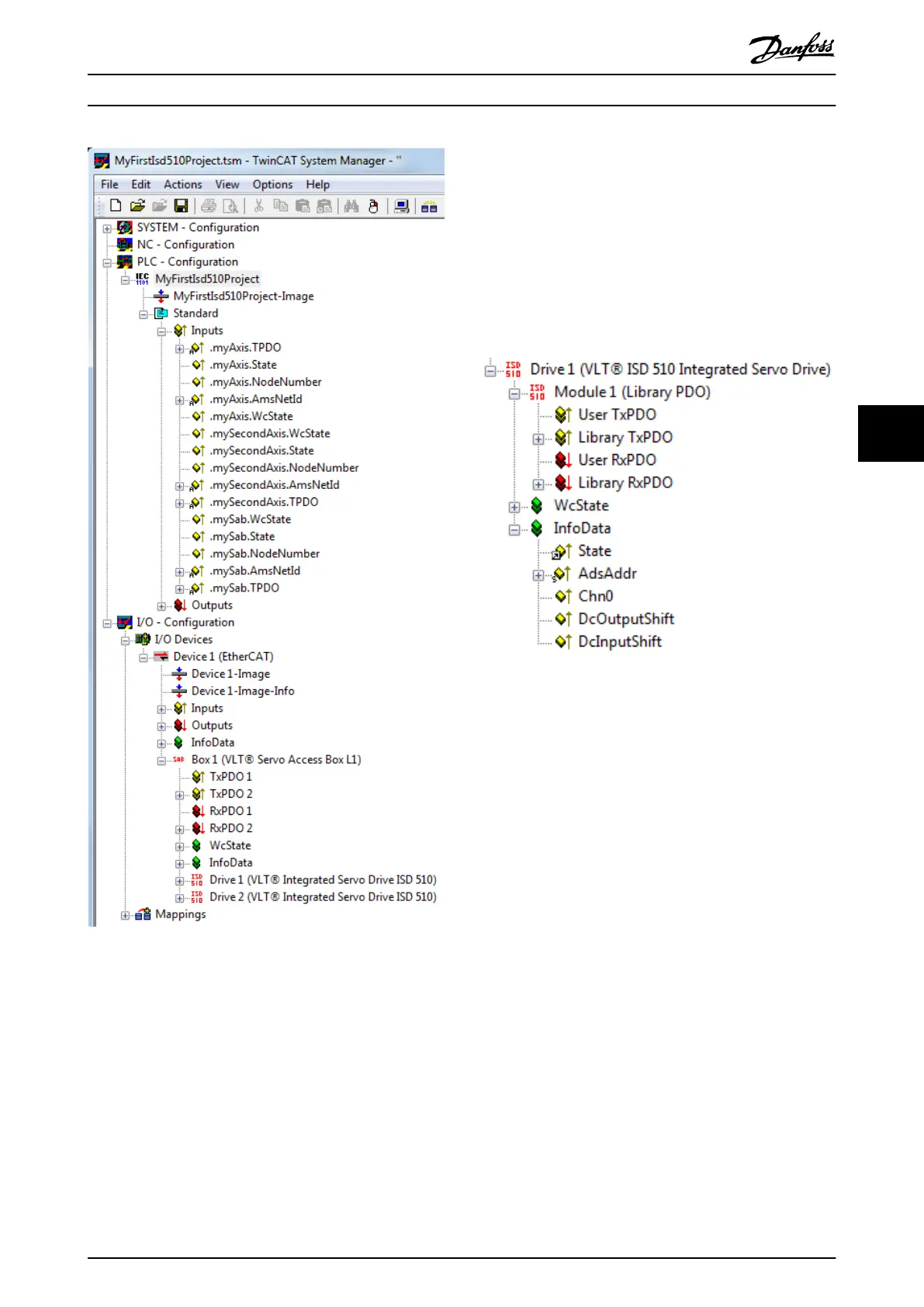
Illustration 6.5 TwinCAT
®
System Manager after Appending the
PLC Project and Adding an SAB and 2 Servo Drives
I/O conguration and I/O mapping
When connecting >1 servo drive, connect port C (X2) of
the previous servo drive to port A (X1) of the next servo
drive. Also make the port assignment for the SAB. If the
hardware set-up is already present, the TwinCAT
®
System
Manager Scan devices function can be used to automat-
ically add the connected devices to the conguration in
the correct order.
Congure the servo drive, so that the PDO mapping
matches the requirements of the library, via the TwinCAT
®
System Manager.
1. Click on the ISD servo drive entry.
2. Select the Slots tab on the right side of the
window.
3. Remove the current PDO conguration by
selecting the entry Module 1 (CSV PDO) in the Slot
box.
4. Click on X.
5. Select Library PDO in the Module box.
6. Click on <.
Illustration 6.6 ISD 510 Servo Drive with Correct I/O Congu-
ration
Attach the input and output variables of the PLC program
to the physical inputs and outputs of the device. Use the
TwinCAT
®
System Manager for this so that the library has
access to all necessary objects.
1. Select Library TxPDO via menu [I/O-Conguration
→ I/O Devices → Device1 (EtherCAT
®
) → Box 1
(VLT
®
Servo Access Box L1) → Drive 2 (VLT
®
ISD
510 Integrated Servo Drive) → Module 1 (Library
PDO) → Library TxPDO].
2. Select all entries Lib pdo tx1 to Lib pdo tx9 on the
right side of the window (see Illustration 6.7).
3. Right-click and select Change Multi Link….
4. In the Attach Variable 36.0 Byte(s) (Input) window,
select [PLC-Conguration → MyFirstIsd510Project
→ Standard → .myAxis.TPDO].
Ensure that the Matching Size option is selected
in the Attach Variable window.
5. Click on OK.
6. Click on library RxPDO via menu [I/O-Congu-
ration → I/O Devices → Device1 (EtherCAT
®
) →
Box1 (VLT
®
Servo Access Box L1) → Drive2 (VLT
®
ISD 510 Integrated Servo Drive) → Module1
(Library PDO) → Library RxPDO].
Programming Programming Guide
MG36D102 Danfoss A/S © 01/2017 All rights reserved. 165
6
6

 Loading...


