7. Select all entries Lib pdo rx1 to Lib pdo rx9 on the
right side of the window.
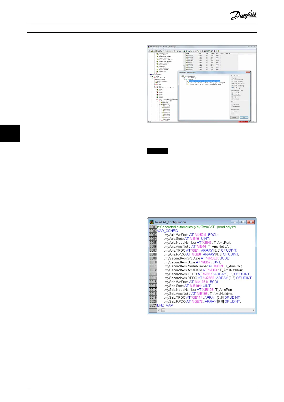
8. Right-click and select Change Multi Link….
9. In the Attach Variable 36.0 Byte(s) (Output)
window, select [PLC-Conguration →
MyFirstIsd510Project → Standard → .myAxis.RPDO].
10. Click on OK.
11.
Right-click on WcState via [I/O-Conguration →
I/O Devices → Device1 (EtherCAT
®
) → Box1 (VLT
®
Servo Access Box L1) → Drive2 (VLT
®
ISD 510
Integrated Servo Drive) → WcState] and select
Change Link….
12. In the Attach Variable State (Input) window, select
[PLC-Conguration → MyFirstIsd510Project →
Standard → .myAxis.WcState].
13. Click on OK.
14.
Right-click on State via
[I/O-Conguration → I/O
Devices → Device1 (EtherCAT
®
) → Box1 (VLT
®
Servo Access Box L1) → Drive2 (VLT
®
ISD 510
Integrated Servo Drive) → InfoData] and select
Change Link….
15. In the Attach Variable State (Input) window, select
[PLC-Conguration → MyFirstIsd510Project →
Standard → .myAxis.State.
16. Click on OK.
17.
Right-click on netId via [I/O-Conguration → I/O
Devices → Device1 (EtherCAT
®
) → Box1 (VLT
®
Servo Access Box L1) → Drive2 (VLT
®
ISD 510
Integrated Servo Drive) → InfoData → AdsAddr]
and select Change Link….
18. In the Attach Variable netId (Input) window, select
[PLC-Conguration → MyFirstIsd510Project →
Standard → .myAxis.AmsNetId].
19. Click on OK.
20.
Right-click on port via [I/O-Conguration → I/O
Devices → Device1 (EtherCAT
®
) → Box1 (VLT
®
Servo Access Box L1) → Drive2 (VLT
®
ISD 510
Integrated Servo Drive) → InfoData → AdsAddr]
and select Change Link….
21. In the Attach Variable port (Input) window, select
[PLC-Conguration → MyFirstIsd510Project →
Standard → .myAxis.NodeNumber].
22. Click on OK.
Illustration 6.7 Attaching Inputs and Outputs to the Physical
Data Points
NOTICE
Repeat the steps 2–22 for Box 1 (VLT
®
Servo Access Box
L1) and the instance mySAB.
To transfer the mappings back to the PLC program, select
Activate Conguration… in menu item Actions.
After a rebuild in TwinCAT
®
PLC Control, the TwinCAT
®
conguration is according to Illustration 6.8 (here myAxis
and mySecondAxis are instances of AXIS_REF_ISD51x and
mySAB is an instance of SAB_REF). The concrete addresses
can be dierent.
Illustration 6.8 TwinCAT
®
Conguration: I/O Mapping of 2
Servo Drives and 1 SAB
Programming
VLT
®
Integrated Servo Drive ISD
®
510 System
166 Danfoss A/S © 01/2017 All rights reserved. MG36D102
6
6

 Loading...


