NOTICE
Put the SAB to a separate SYNC unit to avoid
interruptions in communication to the SAB if the U
AUX
supply to the servo drives is switched o due to an error.
Cycle time settings
The minimum cycle time is 400 µs. The ISD 510 devices
can run EtherCAT
®
cycle times in multiples of 400 µs or
500 µs. The devices are automatically parameterized by the
PLC on start-up, depending on the EtherCAT
®
conguration
of the physical interface. To access the system base time,
select
[SYSTEM-Conguration → Real-Time Settings] in the
TwinCAT
®
System Manager. Multiples of this base time can
then be used as EtherCAT
®
cycle times.
NOTICE
Set the task cycle time of the PLC program to be the
same as the EtherCAT
®
cycle time. Otherwise data can
get lost and performance is reduced.
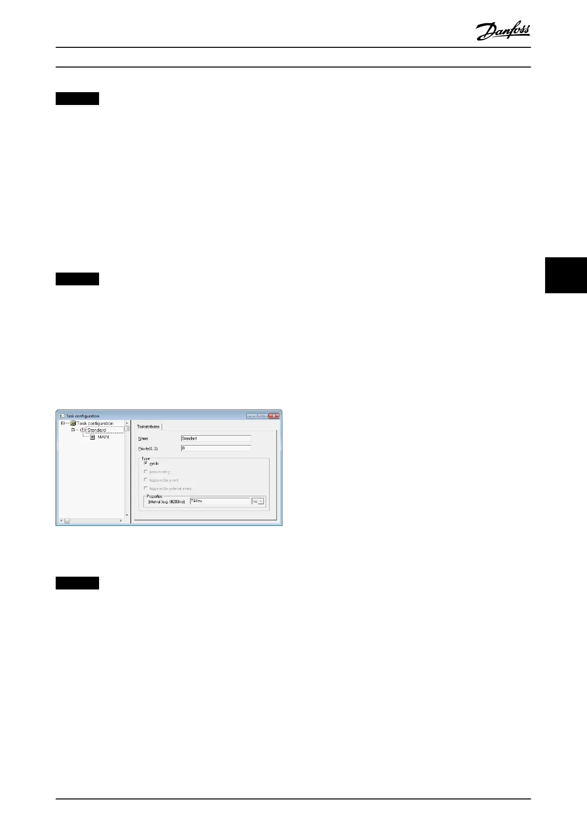
Set the PLC cycle time in TwinCAT
®
PLC Control:
1. Double-click Task conguration in the Resources
tab.
2. Ensure that the PLC cycle time is the same as the
EtherCAT
®
cycle time.
Illustration 6.9 Task Conguration to Parameterize PLC Cycle
Time
NOTICE
After changing the task cycle time in TwinCAT
®
PLC
Control, carry out a ReScan of the PLC conguration
inside the TwinCAT
®
System Manager to update the
settings. Afterwards, activate the conguration in the
PLC.
6.3.1.3
Conguration as a TwinCAT
®
NC
Axis
The servo drives can be used with the built-in NC
functionality of TwinCAT
®
. Everything related to the SAB
must be done as described in chapter 6.3.1.2 Creating a
TwinCAT
®
Project.
1. In addition to the Danfoss_VLT_ISD_510.lib le,
include the TcMC2.lib le (the
Danfoss_VLT_ISD_510.lib le is still needed for the
SAB to be operated).
2. Create 1 instance of AXIS_REF (instead of
AXIS_REF_ISD51x) for each servo drive that is used
as an NC axis.
3.
Append the PLC project into the TwinCAT
®
System
Manager, import the devices, and add them to
TwinCAT
®
as described in chapter 6.3.1.2 Creating
a TwinCAT
®
Project, however in the last step,
answer the question if the servo drive is used as
an NC axis with Yes. Then an NC task is created
automatically.
In the TwinCAT
®
System Manager, select a dierent I/O
Conguration for the servo drives used as NC axes.
1. Depending on the mode of operation to be used,
select either the slot CSP PDO or CSV PDO. Per
default, CSV PDO is mapped and pre-selected.
Map the following variables if the servo drive is
required to work with CSP PDO:
1a In the Settings Tab of the NC Axis, select
[NC-Conguration → NC-Task 1 SAF →
Axes → Axis 1]. Click on the Link To (all
Types)… button and select the desired
servo drive.
2. In the same tab, select the preferred Unit.
3. Depending on the selected Unit, adjust the
Scaling Factor for the axis encoder via menu [NC-
Conguration → NC-Task 1 SAF → Axes → Axis 1 →
Axis 1_Enc] in the Parameter tab.
Example: When the unit Degrees is selected, the
scaling factor is 360°/2
20
= 0.00034332275390625.
4. Set the Reference Velocity in the Parameter tab via
menu [NC-Conguration → NC-Task 1 SAF → Axes
→ Axis 1 → Axis 1_Enc.
5. Set the Output Scaling Factor (Velocity) to 125.
6. Test the functionality and the
conguration in the
Online tab of the axis.
6.3.1.4 Connecting to the PLC
Information on how to connect to the PLC can be found in
detail in the Beckho Information System
(infosys.beckho.com). Open the information system and go
to [TwinCAT 2 → TwinCAT System Manager → Operation →
Controls → Choose Target System].
Programming Programming Guide
MG36D102 Danfoss A/S © 01/2017 All rights reserved. 167
6
6

 Loading...


