1.
Select the menu entry [Tools → Import Fieldbus
Device…].
2. Select the XDD le 0x0300008D_ISD510.xdd from
its location on the hard drive.
This import only needs to be done once per
project. The device is then known to Automation
Studio™.
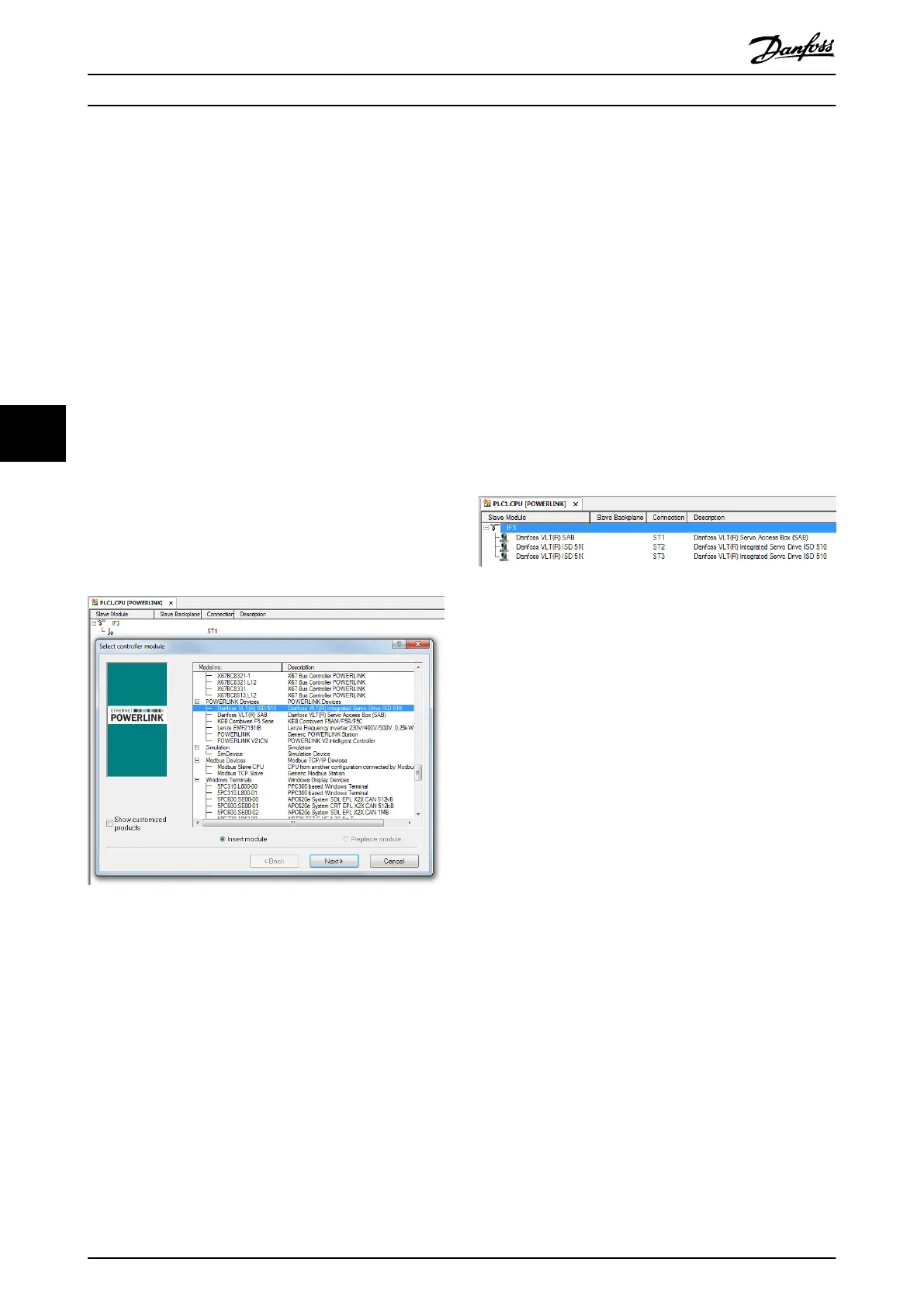
3. The ISD 510 servo drive can now be added to the
Ethernet POWERLINK
®
interface of the controller
in the Physical View:
3a Right-click on the controller in the
Physical View and select [Open →
POWERLINK].
3b Right-click on the interface and select
Insert….
3c In the Select controller module window,
select the ISD 510 in the group
POWERLINK Devices.
3d Click on Next.
3e In the next window, enter the node
number of the servo drive.
Illustration 6.12 Add an ISD 510 Servo Drive to the Project
For each physical servo drive, add 1 entry to the Physical
View of Automation Studio™.
The next step is to import the Servo Access Box into
Automation Studio™:
1.
Select the menu entry [Tools → Import Fieldbus
Device…].
2. Select the XDD le 0x0300008D_SAB.xdd from its
location on the hard drive. This import only
needs to be done once per project. The device is
then known to Automation Studio™.
3. The SAB can now be added to the Ethernet
POWERLINK
®
interface of the controller in the
Physical View:
3a Right-click on the controller in the
Physical View and select [Open →
POWERLINK].
3b Right-click on the interface and select
Insert….
3c In the Select controller module window,
select the SAB in the group POWERLINK
Devices.
3d Click on Next.
3e In the next window, enter the node
number of the SAB.
For each physical SAB, add 1 entry to the Physical View of
Automation Studio™.
Illustration 6.13 1 SAB and 2 ISD 510 Servo Drives Added to
the Ethernet POWERLINK
®
Interface
I/O conguration and I/O mapping
The I/O Conguration of the servo drive has to be parame-
terized in a way that the library has access to all necessary
objects:
1. Right-click on the entry of the ISD 510 and select
Open I/O Conguration.
2. In the Channels section, change the Cyclic
transmission of the following objects:
2a All sub-indexes of object 0x5050 (Lib
pdo rx_I5050 ARRAY[]) to Write.
2b All sub-indexes of object 0x5051 (Lib
pdo tx_I5051 ARRAY[]) to Read.
The I/O Conguration of the SAB has to be parameterized
in a way that the library has access to all necessary
objects:
1. Right-click on the entry of the SAB and select
Open I/O Conguration.
2. In the Channels section, change the Cyclic
transmission of the following objects:
2a All sub-indexes of object 0x5050 (Lib
pdo rx_I5050 ARRAY[]) to Write.
2b All sub-indexes of object 0x5051 (Lib
pdo tx_I5051 ARRAY[]) to Read.
These settings congure the cyclic communication with
the device. These parameters are required for the library to
work.
Programming
VLT
®
Integrated Servo Drive ISD
®
510 System
170 Danfoss A/S © 01/2017 All rights reserved. MG36D102
6
6

 Loading...


