NOTICE
It is possible to use copy & paste to apply the same I/O
Conguration to multiple devices of the same type.
NOTICE
Set Module supervised to o for the servo drives and the
SAB. The parameter is found in the I/O Conguration of
the device.
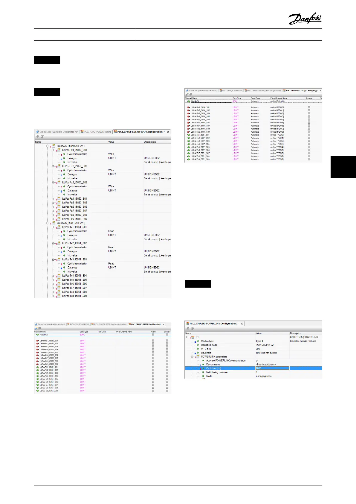
Illustration 6.14 I/O Conguration of an ISD 510 Device
Illustration 6.15 I/O Mapping after Successful Conguration
Map the inputs and outputs of the instance of the
AXIS_REF_ISD51x function block and the physical data
points of the servo drive according to Illustration 6.16 (here
myAxis is an instance of AXIS_REF_ISD51x):
Illustration 6.16 I/O Mapping of an ISD 510 Servo Drive
Map the inputs and outputs of the instance of the SAB_REF
function block and the physical data points of the SAB
accordingly.
Cycle time settings
The minimum cycle time is 400 µs. The ISD 510 devices
can run Ethernet POWERLINK
®
cycle times in multiples of
400 µs and multiples of 500 µs. The devices are automat-
ically parameterized by the PLC on start-up, depending on
the Ethernet POWERLINK
®
conguration of the physical
interface. The Ethernet POWERLINK
®
conguration can be
accessed by right-clicking [CPU → Open IF3 POWERLINK
Conguration] in the Physical View.
NOTICE
Ensure that the task cycle times of the PLC program and
Ethernet POWERLINK
®
are the same. Otherwise, data
could be lost and performance reduced.
Illustration 6.17 Ethernet POWERLINK
®
Conguration Window
to Parameterize Ethernet POWERLINK
®
Cycle Time
Set the PLC cycle time in Automation Studio™:
1.
Right-click [CPU → Open Software Conguration]
in the Physical View.
2. Ensure that the PLC cycle time is the same as the
Ethernet POWERLINK
®
cycle time.
Programming Programming Guide
MG36D102 Danfoss A/S © 01/2017 All rights reserved. 171
6
6

 Loading...


