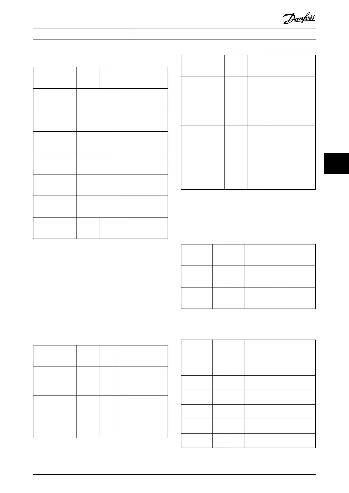
DD_BASIC_CAM_ISD51x
Variable name Data
type
Defaul
t
value
Description
MasterScaling DD_FACTOR_ISD5
1x
Parameters for master
scaling.
See Table 6.66.
SlaveScaling DD_FACTOR_ISD5
1x
Parameters for slave
scaling.
See Table 6.66.
ControlParame-
terSet1
DD_CONTROL_PA
RAMETER_ISD51x
Parameters for control
parameter set 1.
See Table 6.67.
ControlParame-
terSet2
DD_CONTROL_PA
RAMETER_ISD51x
Parameters for control
parameter set 2.
See Table 6.67.
FollowingError DD_FOLLOWING_
ERROR_ISD51x
Parameters for
following error set-up.
See Table 6.68.
DataPoints ARRAY of
DD_DATA_POINT_
ISD51x
Array of data points for
the basic CAM.
See Table 6.65.
NumberOfData-
Points
UINT 0 Gives the number of
used data points inside
the array.
Table 6.64 DD_BASIC_CAM_ISD51x
The basic CAM consists of header information, such as
master and slave scaling, control parameter sets 1 and 2,
and error parameters. The parameters are optional within
the le. If all the subelements of 1 structure are 0, the
element is not created within the CAM le.
The data points, which dene the functionality of the CAM,
are kept in an array of data points. The number of data
points used must be written to the variable NumberOfDa-
taPoints. Each data point contains the elements shown in
Table 6.65.
DD_DATA_POINT_ISD51x
Variable name Data
type
Defaul
t
value
Description
MasterPosition REAL 0 Master position for this
data point. Given in
revolutions of guide
value. Value range: 0–1.
SlavePosition REAL 0 Axis position for this
data point. Given in
revolutions of rotor
position. This is the
position at gear in
(motor side).
Variable name Data
type
Defaul
t
value
Description
Velocity REAL 0 Velocity of the axis in
this data point. The
velocity must be given
as a factor between the
velocity of the axis in
relation to the velocity
of the guide value.
Acceleration REAL 0 Acceleration of the axis
in this data point. The
acceleration must be
given as a factor
between the
acceleration of the axis
in relation to the
velocity of the guide
value.
Table 6.65 DD_DATA_POINT_ISD51x
For this structure, the optional elements (Velocity and
Acceleration) are always written to the le as they do not
change the behavior.
DD_FACTOR_ISD51x
Variable
name
Data
type
Defau
lt
value
Description
Numerator DINT 0 Numerator part of the factor. 2
negative values result in a
positive factor.
Denominator DINT 0 Denominator part of the factor. 2
negative values result in a
positive factor.
Table 6.66 DD_FACTOR_ISD51x
DD_CONTROL_PARAMETER_ISD51x
Variable
name
Data
type
Defau
lt
value
Description
SpeedP REAL 0 Proportional part of the speed
controller.
SpeedI REAL 0 Integral part of the speed
controller.
SpeedD REAL 0 Dierential part of the speed
controller.
Inertia REAL 0 Inertia used for feed-forward
calculations. [kg m²]
PositionP REAL 0 Proportional part of the position
controller.
PositionD REAL 0 Dierential part of the position
controller.
Table 6.67 DD_CONTROL_PARAMETER_ISD51x
Programming Programming Guide
MG36D102 Danfoss A/S © 01/2017 All rights reserved. 219
6
6

 Loading...


