between logical and absolute rotor angle is established or
re-established. This is useful, if the axis has to be moved to
an absolute position after a loss of the reference position
by using a variable movement (for example, MoveDistance-
Segment).
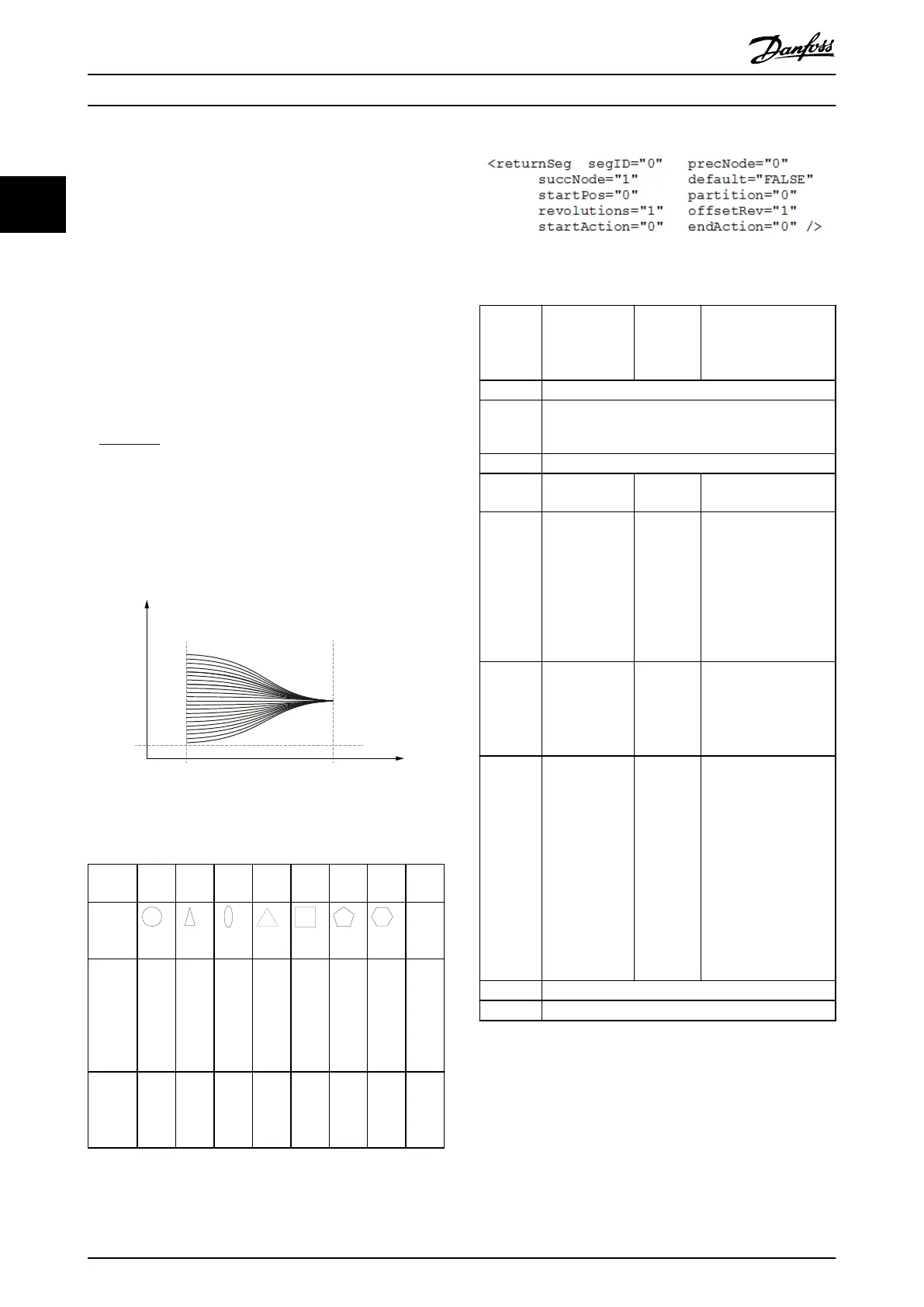
Usually the ReturnSegment is used at the beginning of the
CAM to start from a dened absolute position. The Return-
Segment is used in conjunction with devices which have
multiple, equidistant, and equivalent starting positions, for
example, a square device.
The axis automatically selects the shortest way and
calculates a polynomial of 5
th
degree to reach the next
valid position. A backward movement of the servo drive is
possible. Valid positions are calculated by the formula:
+ osetRev
partition
revolutions
The ReturnSegment should be the rst segment in a CAM
prole. It provides a means to return to the next
equivalent starting position and eliminate all rounding
errors. This segment must always start in standstill and it
also stops in standstill.
Guide
value
Rotor angle
of axis
startPos
succNodeprecNode
130BF295.10
End position
depends on the
position at the start
of the segment and
the parameters
Illustration 2.91 Return Segment
Partitio
n
0 1 2 3 4 5 6 ...
Possibl
e
shapes
valid
phys.
rotor
angles
each 0° 0°
180°
0°
120°
240°
0°
90°
180°
270°
0°
72°
144°
216°
288°
0°
60°
120
180°
240°
300°
worst
case
angle
to turn
0° ±180° ±90° ±60° ±45° ±36° ±30°
Table 2.23 Partition Example of ReturnSegment for
Single-turn Axis (revolutions = 1; osetRev = 0)
Illustration 2.92 Start/Endpoint Representation
Attribute Mandatory/
optional
(+default
value)
Value
range/
allowed
values
Description
segID Same as in Table 2.17.
precNode Same as in Table 2.17.
succNode Same as in Table 2.17.
startPos O Float See Table 2.18 for type=
relative.
partition O; default = 0 Integer:
(0;16)
Can be used for shaped
plates when several
equal, valid starting
positions are allowed.
The worst case
movement is
inuenced by this
parameter.
revolutions O; default = 1 Integer >0 Number of revolutions
that are used when
calculating valid
positions, for example,
if there is a gear.
osetRev O; default = 0 Float Desired end rotor
position relative to the
nearest physical
position. The reference-
position is determined
by the absolute
position at the
beginning of this
segment and the
partition/revolutions.
Given in revolutions of
the axis.
startAction Same as in Table 2.17.
endAction Same as in Table 2.17.
Table 2.24 Attributes for ReturnSegment in Start/Endpoint
Representation
Coecient representation: This representation is not
available.
EventSegmentContainer:
The EventSegmentContainer embeds a time-related
movement (composed by EventNodes and EventSegments)
into the guide value-related process. It provides a certain
Servo Drive Operation
VLT
®
Integrated Servo Drive ISD
®
510 System
60 Danfoss A/S © 01/2017 All rights reserved. MG36D102
22

 Loading...


