Blending ends inside segment with undetermined end position
If the segment has an undetermined end position (see
Table 2.34), the blending distance is extended to the end of
the segment. The blending is done to the preceding node
of the segment.
Guide value
cycle
Rotor angle of axis
0
1
2
Change CAM imm=0
Use blend dist=1
Master absolute
Starting
Node
Blending
blend
dist
Segment with
undetermined
end position
Illustration 2.108 Blending Ends inside a Segment with
Undetermined End Position.
The blending is extended to the next node. The blending
behavior then depends on the node.
A special case is the GuidePoly of type relative. Here, the
servo drive calculates a P4 to adjust the velocity and the
acceleration to match at the point where the blending
distance ends. The position is not relevant here.
Guide value
cycle
Rotor angle of axis
0
1
2
Change CAM imm=0
Use blend dist=1
Master absolute
Starting
Node
Blending
using a P4
blend
dist
relative
GuidePoly
Illustration 2.109 Blending Ends inside a GuidePoly of Type
Relative.
The blending distance is as specied.
The slave position is not relevant here, but is determined
automatically by the P4 that is calculated by the servo
drive to adjust the velocity and acceleration.
Blending ends at a node
The behavior is all the same, independent if this node is
the starting node of a CAM, or some other node. It is also
the same, if the blending distance has been extended to
the node or not. When blending to a node, the following
segment of this node is relevant.
For the EventSegmentContainer, the rst EventSegment is
relevant. If the following segment is a segment with a
determined start position (see Table 2.34), a P5 is used to
blend to this position.
If the following segment is a segment with an
undetermined start position (see Table 2.34), the servo
drive calculates a P4 to do the blending in order to adjust
the velocity and acceleration of this start condition. The
slave position itself is not relevant.
A CAM error is issued if there is no following segment to a
node (as it is for example: the last node of a non-cyclic
CAM).
Actions
A list of actions can be attached to several events. These
events can be:
•
A node.
•
The beginning of a segment.
•
The end of a segment.
The order of executing actions when processing segment
A, node B, and segment C is the following:
•
Start actions of segment A.
•
End actions of segment A.
•
Actions of node B.
•
Start actions of segment C.
•
End actions of segment C.
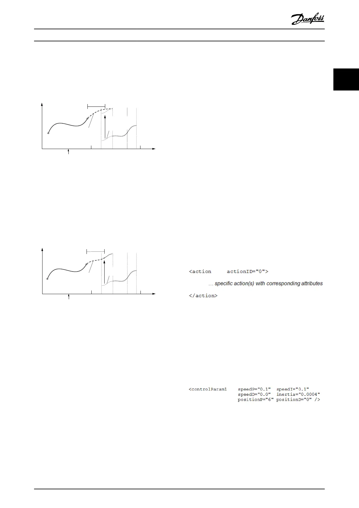
An action is described with a surrounding element to
dene an actionID which is used for referencing inside the
CAM prole. This actionID must be unique across all
dened actions. Inside this action element, there can be 1
or more sub-elements.
Available actions are listed in the following sub-chapters.
Illustration 2.110 Actions
Action: Change set of control loop parameters
To dene an action that changes a set of control
parameters, the following element must be inserted inside
the action. The denition and value ranges are equal to
the general denition of a control parameter set within a
CAM prole.
To change the control parameters for the 1
st
set use:
Illustration 2.111 Control Parameters for Set 1
Servo Drive Operation Programming Guide
MG36D102 Danfoss A/S © 01/2017 All rights reserved. 69
2 2
 Loading...


