130BF297.10
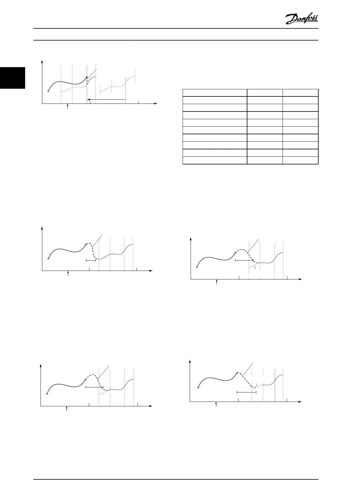
Guide value
cycle
Rotor angle of axis
0
1
2
Change CAM imm=0
Use blend dist=0
Starting
Node
Master relative
Master relative
Possible jump in
position and velocity
Illustration 2.103 Blending is Done to the Starting Node of the
CAM; Master Relative.
Jump depends on the following segment of the starting node
of the CAM.
•
When option Use blend distance = 1, there are 2
possible cases:
- Minimum blending distance ends before
the CAM denition starts: The blending
distance is extended to the next node
(seen from the current guide value
position, based on the default CAM).
Guide value
cycle
Rotor angle of axis
0
1
2
Change CAM imm=0
Use blend dist=1
Starting
Node
Master absolute
Blending
blend dist
Illustration 2.104 Blending is Extended to the Next GuideNode
(not necessarily the starting node)
-
Minimum blending distance ends within
a segment: The behavior depends on
the segment type where the blending
would end (see the following sub-
chapters).
Guide value
cycle
Rotor angle of axis
0
1
2
Change CAM imm=0
Use blend dist=1
Master absolute
Starting
Node
Blending
blend
dist
Illustration 2.105 Minimum Blending Distance Ends within a
Segment
The blending behavior depends on the segment type
where it ends (see Table 2.34). In Illustration 2.105, the
blending is extended to the next GuideNode (not
necessarily the starting node).
Segment type Start position End position
GuidePoly of type absolute determined determined
GuidePoly of type relative undetermined undetermined
MoveDistanceSegment undetermined undetermined
FlyingStopSegment undetermined undetermined
ReturnSegment undetermined determined
EventSegmentContainer undetermined undetermined
TimePoly of type absolute determined determined
TimePoly of type relative undetermined undetermined
All other EventSegments undetermined undetermined
Table 2.34 Segment types and their Classications of Start
and End Position
Blending ends inside segment with determined end position
If the segment is a segment with a determined end
position (see Table 2.34), the blending distance is extended
to the end of the segment and the blending is done to
this absolute (determined) position.
Guide value
cycle
Rotor angle of axis
0
1
2
Change CAM imm=0
Use blend dist=1
Master absolute
Starting
Node
Blending
blend
dist
Return
Segment
Illustration 2.106 Blending Ends inside a Segment with
Determined End Position (Here: ReturnSegment)
A special case is the
GuidePoly of type absolute. Here, the
whole segment (not only the end position) is determined.
So for GuidePolys the blending distance is not extended.
Guide value
cycle
Rotor angle of axis
0
1
2
Change CAM imm=0
Use blend dist=1
Master absolute
Starting
Node
Blending
blend
dist
absolute
GuidePoly
Illustration 2.107 Blending Ends inside a GuidePoly of Type
Absolute.
The blending is done to that exact position.
Servo Drive Operation
VLT
®
Integrated Servo Drive ISD
®
510 System
68 Danfoss A/S © 01/2017 All rights reserved. MG36D102
22
 Loading...


