Attribute Mandato
ry/
optional
(+default
value)
Value
range/
allowed
values
Description
acceleration M Float >0 Acceleration of the axis
when increasing the
velocity. The acceleration
must be given in rps per
second. It is possible to
parameterize jumps in
the acceleration when 2
succeeding segments
have dierent startAcc
and endAcc values.
deceleration O;
default =
value of
accelerati
on
Float >0 Deceleration of the axis
when decreasing the
velocity. The deceleration
must be given in rps per
second. It is possible to
parameterized jumps in
the deceleration when 2
succeeding segments
have dierent startAcc
and endAcc values.
timeout M Uint32 Timeout in ms for
reaching guideValue
oset and start of
measuring.
guideValue M Float 0–
0.9999
guideValue Oset for
starting the measuring.
exitCond Same as in Table 2.26.
startAction Same as in Table 2.26.
endAction Same as in Table 2.26.
Table 2.33 Attributes for FrictionSegment in Start/Endpoint
Representation
Coecient representation: This representation is not
available.
Switching between CAM proles
Depending on the CAM conguration option master
abs/rel and especially on the advanced CAM itself, there
are several ways to go from 1 running CAM prole to the
next. All the possibilities are described in the graphics in
this section.
The following examples all show the starting point based
on the time of the CAM activation request, respectively
when CAM ack (bit 12) is set by the axis (see
chapter 2.4.5.5 Advanced CAM).
In the following sub-chapters, it is assumed, that the servo
drive is already running on the rst shown CAM. The
behavior that is interesting here is the transition to the
second (advanced) CAM based on the point of activation
request and the conguration of the second (advanced)
CAM.
All illustrations in the following sub-chapters show the
transition from a currently running CAM 2 (see
Illustration 2.41) to a newly activated CAM.
The following conventions are basically used for transitions
between proles:
•
If a CAM prole is aborted (Change CAM
imm = 1), the current slave position is considered
as end slave position.
•
Master absolute uses the GuideNode positions as
specied in the CAM.
•
Master relative moves the starting node of the
CAM (nodeID = 0) to the end point of the
previous CAM. This can be the end position or
the point where it has been aborted (using
Change CAM imm = 1), see Illustration 2.102).
•
When activating a non-cyclic CAM prole with
Use blend distance = 0, the processing of it takes
place in the same master cycle (as the CAM
activation request) or in the next one (depending
on the end point of the currently running CAM
prole and the starting node of the new CAM
prole). In both cases, the CAM is processed as 1
complete cycle (starting with the next upcoming
starting node).
•
When activating a non-cyclic CAM prole with
Use blend distance = 1, the processing of (at least
the starting node) it takes place in the same
master cycle (as the CAM activation request) or a
CAM error is issued. This means that the starting
node must be in the same master cycle.
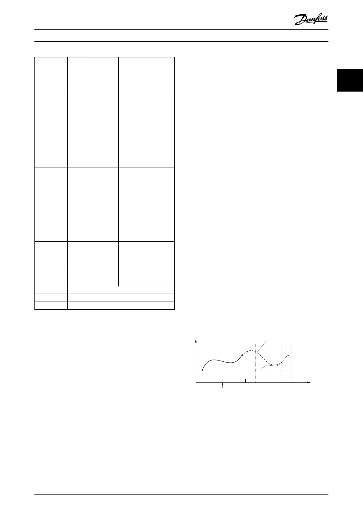
•
When option Use blend distance = 0, it leads to a
blending to the starting node of the CAM
(nodeID = 0). However, this is not necessarily the
next node (seen from the current guide value
position).
Guide value
cycle
Rotor angle of axis
0
1
2
Change CAM imm=0
Use blend dist=0
Master absolute
Starting
Node
Blending
Illustration 2.102 Blending is Done to the Starting Node of the
CAM; Master Absolute
Servo Drive Operation Programming Guide
MG36D102 Danfoss A/S © 01/2017 All rights reserved. 67
2 2
 Loading...


