Attribute Mandatory/
optional
(+default
value)
Value range/
allowed values
Description
velocity
Limit
O; default =
maximum
Float >0 Congures the
maximum velocity
that can be used
during this
segment (absolute
value). The
velocity must be
given in rps.
When limit is
reached, no more
torque is
generated until
velocity is below
limit again.
exitCond Same as in Table 2.26.
startAction Same as in Table 2.26.
endAction Same as in Table 2.26.
Table 2.31 Attributes for TorqueSegment in Start/Endpoint
Representation
Coecient representation: This representation is not
available.
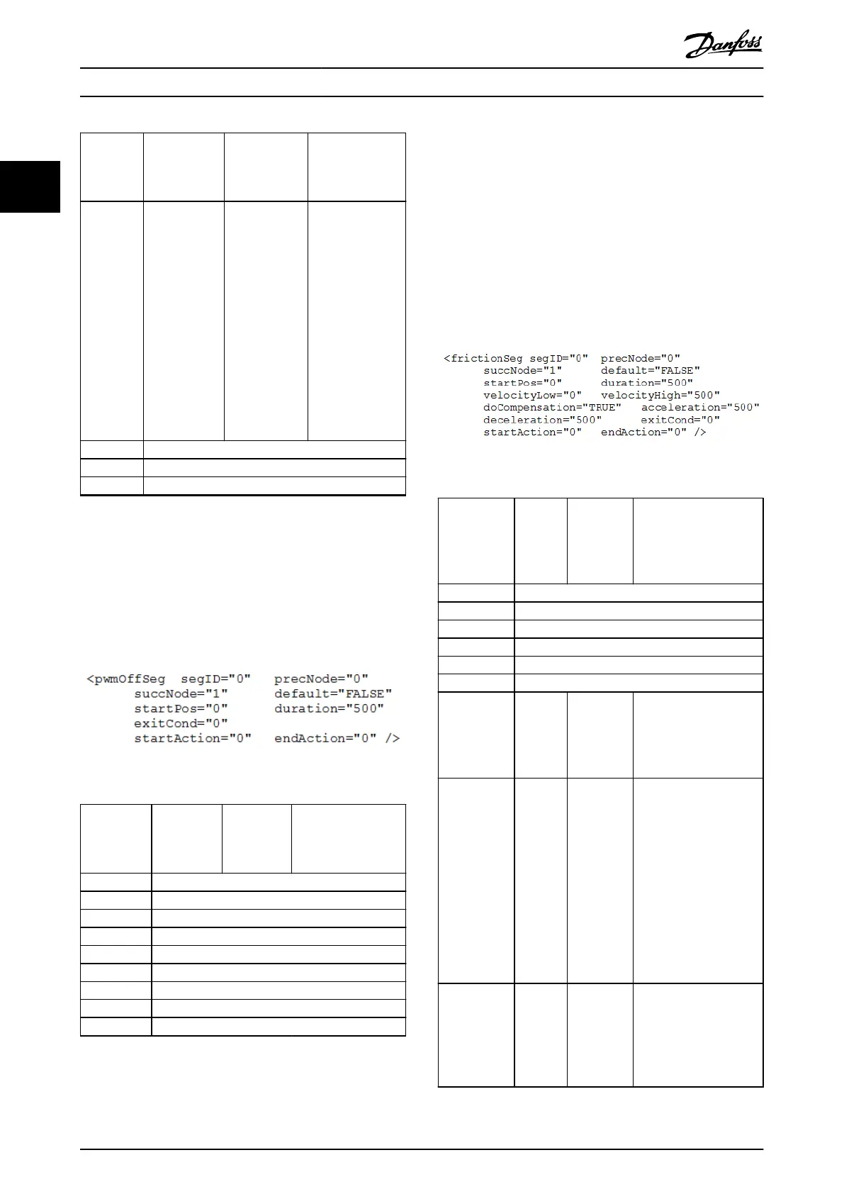
PwmOSegment:
The PwmOSegment is used to turn o the PWM. Enabling
the PWM again afterwards takes some time.
Illustration 2.100 Start/Endpoint Representation
Attribute Mandatory/
optional
(+default
value)
Value
range/
allowed
values
Description
segID Same as in Table 2.26.
precNode Same as in Table 2.26.
succNode Same as in Table 2.26.
default Same as in Table 2.26.
startPos Same as in Table 2.18.
duration Same as in Table 2.26.
exitCond Same as in Table 2.26.
startAction Same as in Table 2.26.
endAction Same as in Table 2.26.
Table 2.32 Attributes for PwMOSegment in Start/Endpoint
Representation
Coecient representation: This representation is not
available.
FrictionSegment:
The FrictionSegment is used to rst measure the friction of
the servo drive system at 2 dierent velocities. This friction
can either be used for long-term monitoring or the servo
drive can use it for an automatic compensation. The
measurement occurs alternating (over the guide value
cycles) with velocityLow and with velocityHigh.
This segment ends either with the dened velocityLow or
velocityHigh.
Illustration 2.101 Start/Endpoint Representation
Attribute Mandato
ry/
optional
(+default
value)
Value
range/
allowed
values
Description
segID Same as in Table 2.26.
precNode Same as in Table 2.26.
succNode Same as in Table 2.26.
default Same as in Table 2.26.
startPos Same as in Table 2.18.
duration Same as in Table 2.26.
velocityLow M Float Velocity of the axis
during the rst part of
the measurement. The
velocity must be given
in rps.
velocityHigh O; no
default
exists
Float Velocity of the axis
during this segment. The
velocity must be given
in rps. To ensure smooth
movements, the
velocities of all segments
that are connected in
the same node should
be the same. If this is
not parameterized
correctly, a jump in
velocity will occur.
doCompen-
sation
O;
default =
FALSE
TRUE/FALSE If TRUE, the measured
friction is compensated
automatically by the
servo drive. If FALSE, the
value can be used for
diagnostics.
Servo Drive Operation
VLT
®
Integrated Servo Drive ISD
®
510 System
66 Danfoss A/S © 01/2017 All rights reserved. MG36D102
22

 Loading...


